


Multi-cylindered Two-stroke Engine
Page 74
If you've noticed an error in this article please click here to report it so we can fix it.
A HORIZONTAL two-stroke engine rI forms the subject of patent No. 861,769. It is of the type in which two side-by-side cylinders share a common combustion chamber in the head. (T. Reid, " Crowmere," Bellmere Road, Hampton-in-Arden, Warwicks.)
Referring to the drawing, it will be seen that two crankpins are employed, synchronism being ensured by gearing (1). Only otie connecting-rod runs on a crankpin, the other being pivoted on the first at the point (2).
The gearing and arrangement of pistons is claimed to give a 'good horizontal balance and it is also claimed that the engine is substantially free from vibration.
Each cylinder is provided with a wall port (3) extending completely around the cylinder except where it is bridged by guide bars. The ports in the upper cylinders are for the exhaust and those in the lower ones inlets. A common combustion chamber is shown at 4. As there is no significant change in the volume of the crankcase, an external compressor charges the cylinders.
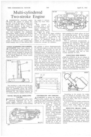
SAFETY BARRIERS FOR LORRIES ACCIDENTS have been known to ITh occur through violent braking causing a load to slide forwards into the cab. A safety barrier designed to Prevent this is shown in patent No. 861,563. (W. Tuck and I. Estop, Ilighcroft, Forest Green, Nailsworth, Glos.) The drawing is a side view of the proposed barrier. It comprises a main upright plate (1) extending across the frame. Reinforcement is provided by ribs (2) and buttresses (3). The bottom brackets (4) are riveted, bolted or welded to the frame.
NOVEL MEANS OF OPERATING VALVES
PATENT No. 861,291 deals with a valve operating mechanism for an aircooled engine. (Humber, Ltd., and J. Shorter, Stoke, Coventry). In the drawing one cylinder is shown diagrammatically of a flat-twin engine in section. The valves are opened by push-rods (1) and the patent deals with a substitute for the conventional rocker. It consists of a piece of rectangular-section rod (2)which is curved to an accurate radius so that it can slide freely in correspondingly curved grooves in the sides of a cast-iron block on the head. A U-shaped pressing is used to cover the grooves and a steel-backed white-metal-lined strip provides a bearing surface. Valve clearance adjustment is by the use of shims fitted beneath the block.
An advantage of the design is that cooling fins can be carried up to the top of the head and around the valves.
A CCORDING to patent No. 861,621, In air-cooled engines with unregulated cooling are often uneconomic because a large proportion of running is done either too hot or too cool. A scheme for regulating automatically the air flow to maintain a constant optimum temperature forms the subject of the patent. (Tatra Narodni P odn a k, Koprivnice, Czechoslovakia.)
The drawing shows a four-cylindered engine in which the air flow is created by a fan (1). The fan drive includes a fluid coupling (2) which utilizes oil from the lubricating system. If the coupling is starved of oil, then slip will result, slowing the fan and increasing the engine temperature.
This is performed automatically; a thermostat (3) controls a slide-valve (4) which in turn determines the quantity of oil flowing to the coupling. The thermostat is located in the exhaust pipe or in the stream of hot air flowing from the cylinders. An alternative scheme uses a bi-metallic strip and an electrically operated oil valve.
INDUCTION PIPE DESIGN r1SCILLATIONS of the air column in '1/4j,
an induction system can, by careful design, be made to increase the charging efficiency. This, however, usually calls for an induction pipe of considerable length. A means of achieving the same end without long pipes is disclosed in patent No. 862,261 (Daimler-Benz A.G., Stuttgart-Unterffirkheim, Germany.)
According to this patent, the intake pipe. (I) should be provided with a flat face on the side from which the individual pipes are taken. This face is shown in the drawing at 2.
It is stated-that this simple modification results in a substantial power increase over a small speed range, with lesser increases over a wider range of speeds.
REDUCING BRAKE NOISE
ieliminate noise from brakes, patent . TID\To. 862,358 proposes to arrange that the lining of the secondary shoe has a lower coefficient of friction than that of the primary shoe. Both linings are made from a sintered mixture of iron powder and graphite, but they differ in detail ingredients. The patent comes from General Motors Corp., Detroit, Michigan, U.S.A.