


Gearbox Lubrication
Page 58
If you've noticed an error in this article please click here to report it so we can fix it.
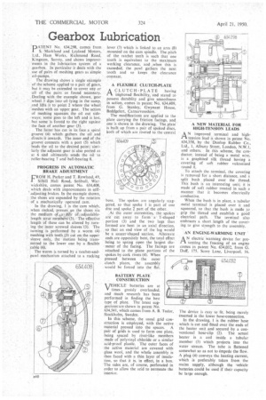
'DIM ENT No. 634,298, comes from I S. Markland and Leyland Motors, Ltd., Ham Works, Richmond Road, Kingston, Surrey, and shows improvements in the lubrication system of a gearbox. In particular it deals with the use of pairs of meshing gears as simple oil-pumps.
The drawing shows a single eiample • of the scheme applied to a pair of gears, but it may be extended to cover any or all of the pairs as found necessary. .Dealing with the example shown, gear 'wheel I dips into oil lying in the sump, and lifts it to point 2 where the wheel meshes with an tipper gear. The action of meshing squeezes, the oil out sideways; some goes to the left and is lost, but some is forced to the right against the face of another gear (3).
The latter 'has cut in its face a spiral groove (4) which. gathers the oil and directs it inwards. The inner end of the groove connects with a port (5) which leads the oil to the desired point; similarly the adjacent gear is also ported as at 6 and ultimately sends the oil to roller-bearing 7 and ball-bearing 8.
PROGRESS IN AUTOMATIC BRAKE ADJUSTMENT
L'ROM H. Parker and T. Rowland, 49,
Silhill Hall Road, Solihull, Warwickshire, comes patent No. 634,408, which deals with improvements in selfadjusting brakes. In the example shown, the shoes are expanded by the rotation of a mechanically operated cam.
In the drawing, I is the cam which, when rocked, presses'. en the shoes via the medium df4allitfir of. adjustablelength strut membirri4(2). The effective length of these can be altered by turning the inner screwed sleeves -(3). The turning is performed by a worm (4) meshing with teeth (5) cut on. the upper sleeve only, the motion being transmitted to the lower one by a flexible ,cable (6).
The worm is turned by a ratchet-andpawl mechanism attached to a rocking lever (7) which is linked to an arm (8) mounted on the cam spindle. The pitch of the ratchet teeth is such that one tooth is equivalent to the maximum working clearance, and when this is exceeded, the pawl gathers the next tooth and so keeps the clearance constant.
A FLEXIBLE CLUTCH-PLATE
A CLUTCH-PLATE having
imp'roved flexibility, and stated to possess durablity and give smoothness in action, comes in patent No. 634,409, from G. Stanley, Gwynant House, Beddgelert, Carnarvonshire.
The modifications are applied to the plate carrying the friction facings, and one is shown in the drawing. The plate' is built up from a pair of spoked discs, both of which are riveted to the central • boss. The spokes are angularly staggered, so that spoke I is part of one disc and spoke 2 part of the other.
At the outer extremities, the spokes are cut away to forma' T-shaped portion (3) and the two lugs thus formed are bent in an axial direction, so that an end view of the lug would be a saucer-shaped section. Alternate ends are oppositely bent, the total effect being to spring open the largest diameter of the facing. The facings are attached to the plane portions of the spokes by cork rivets (4). When pressed between the outer clutch plates, the assembly would be forced into the flat.
BATTERY PLATE CONSTRUCTION
VJEHICLE -batteries are at V times grossly overloaded, arid much research has been performed in finding the best type of plate. The latest suggestions'are shown in patent No. 634,541, which comes from A. B. Tudor, Stockholm, Sweden.
In this scheme, the usual grid construction is employed, with the active material pressed into the spaces. A pair of grids is used to form one plate, being spaced by rivet-like members made of polyvinyl chloride or a similar acid-proof plastic. The outer faces of the active material are covered with glass wool, and the whole assembly is then faced with a thin layer of insulation, so that it is. in effect, in a box. The sides are, of course, perforated in order to allow the acid to permeate the interior. A NEW MATERIAL FOR HIGH-TENSION LEADS
PIA N improved terminal and hightension lead is shown in patent No. 634,358, by the Dunlop Rubber Co., Ltd., 1. Albany Street, London, N.W.I, and others. In this scheme, •the conductor, instead of being a metal wire, is a graphited silk thread having a covering of soft rubber vulcanized round it.
To attach the terminal, the covering is removed for a short distance, and a split bush placed over the thread. This bush is an interesting unit; it is made of soft rubber treated in such a manner that it becomes electrically conductive.
When the bush is in place, a tubular metal terminal is placed over it and squeezed, so that the bush is made to grip the thread and establish a goad electrical path. . The terminal also embraces a short length of the covering to give strength to the assembly.
AN ENGINE-WARMING UNIT
I-1 A N electric warming 'device for preventing the freezing of an engine comes in patent No. 634,032, from G. Duff. 175, Scare Lane, Liverpool, 16.
The device is easy to fit, being merely inserted in the lower hose-connection.
In the drawing, 1 is the rubber hose which is cut and fitted over the ends of the heater unit and secured by a conventional hose-clip (2). The actual heater is a coil inside a tubular member (3) which projects into the water stream. The tube is flattened somewhat so as not to impede the flow. A plug (4) conveys the heating current, which is preferably taken from the mains supply, although the 'vehicle batteries could be used if their capacity be large enough.