


Further Experiments with Infinitely Variable Gears
Page 100
If you've noticed an error in this article please click here to report it so we can fix it.
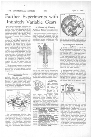
THE .aim of countless inventors has been the infinitely variable gear, and the latest trend appears to be the epicyclic type in which the torque reaction is resisted by the inertia of oscillating masses. Such a gear is disclosed in patent No. 502,133, by Queensland Trustees, Ltd., Brisbane, Australia.
The outer casing (3) represents the flywheel of the engine, whilst the output member is the sun wheel and central shaft. The planet pinion g (4) are pivoted on the casing, and if allowed to revolve, give a speed reduction. Each planet is fitted with an eccentric carrying a connecting rod (2) which is coupled to an oscillating fly-wheel (1). At low speeds these flywheels rock to and fro and so permit the epicyclic reduction, but an increase of speed brings the inertia into play and gradually establishes a direct drive by bringing the planes to a standstill. To assist the maintenance of direct drive, bobweights (5) on the planet -tend to remain stationary under centrifugal force,
The oscillating flywheels are mounted on quick-threaded pivots so that they also oscillate endways, against cushion • springs; this is claimed to smooth out irregularities.
Pneimiatic Suspension System Modifications.
COME time ago we described a LI novel pneumatic suspension system patented by the Firestone Tyre and Rubber Co., Ltd., Great West Road, Brentforcl. This concern now discloses, in patent No. 502,068, certain additions intended to effect lateral, torsional and fore-and-aft stability.
The accompanying drawing illustrates the original features as well as the improvements. The former comprise the use of bellows (1) attached to the axles and carrying the weight of the chassis. An ingenious pendulumoperated air valve automatically controls the inflation of these bellows to suit load, acceleration and cornering.
e64 The improvements consist of pairs of cranked arms (2) integral with the axles, projecting forwardly and upwardly. At the lower points 3, light leaf-springs (4) are attached, the other ends being clamped to the frame. The taps of the arms (2) are pivoted to a one-piece torsion rod (5), which is of C-section and gripped in rubber-bushed clamps (6). The rear axle is fitted up in the same manner, except that the bellows are brought inside the frame.
A Compact Steering Gear.
AN unusually .compact steering gear forms the subject of
patent No.
502,035 by R.
Bishop and R.
Johnson, Kingshub.; House, King Street, Westminster, London. In this design, a single-turn worm engages with a toothed face-cam mounted on the rocker-shaft. The accompanying drawing shows this cam, which is cut by a rotating tool resembling the worm. A modification of the design suggests the cutting of cam teeth on a circle eccen. Injection Pump for High-speed Engines.
APUMP modification by which the commencement of injection is rendered constant, irrespective of the speed of the engine, is shown in patent No. 502,228 by A. Ciano and others, 37, Via Bartolomeo Bosco, Genoa,
The pump cylinder, in this case, is fitted with suction ports (2) and an extra set of fine ports (1). On the upstroke a quantity of fuel is always ejected through the small ports; this subjects the remainder to a. moderate pre-compression until ports 1 have been covered, after which injection takes place in the usual manner.
A Self-energizing Auxiliary Clutch.
A CLUTCH of the self-energizing
type, intended for use behind the gearbox for complete isolation when gear-changing, is shown in patent No. 501,997 by W. Neurath, Franz Josefs Kai 53, Vienna, Austria, In this design, the output shaft of the gearbox is pro vided with a quick thread (4). A male clutch-cone (1) is screwed on the thread, and is spring loaded into engagement with a female cone (2) forming the output member. A roller-type free wheel (3) also couples the clutch members in one direction only.
The free wheel conveys the driving torque, whilst over-running torque is transmitted by the cone clutch, the action of which is self-intensifying by virtue of the screwed coupling. A withdrawal mechanism (5) is coupled to the engine clutch so that one movement of the pedal disconnects the gearbox from engine and road wheels.