


Three New Fuel controlling Pumps
Page 68
If you've noticed an error in this article please click here to report it so we can fix it.
A Résumé of Recently Published Patent Specifications THE controlling of fuel injection would appear to be occupying the attention of inventors at the present time, if the number of patents recently granted for devices of the kind can be taken as an indication.
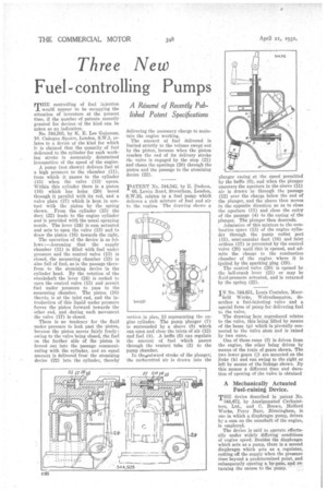
No. 344,503, by K. E. Lee Guinness, 10, Cadogan Square, London, S.W.1, relates to a device of the kind for which it is claimed that the quantity of fuel delivered to the cylinder for each working stroke is accurately determined irrespective of the speed of the engine.
A pump (not shown) delivers fuel at a high pressure to the chamber (11), from which it passes to the cylinder (11I) when the valve (13) opens. Within this cylinder there is a piston '(16) which has licks (20) bored through it parallel with its rod, and a valve plate (17) which is kept in contact -with the piston by the spring shown. From the cylinder (15) the duct (22) leads to the engine cylinder and is provided with the usual spraying nozzle. The lever (24) is cam actuated and acts to open the valve (13) and to draw the piston (16) towards the right.
The operation of the device is as follows :—Assuming that the supply chamber (11) is filled with fuel under pressure and the control valve (13) is closed, the measuring chamber (15) is also full of fuel, as is the passage therefrom to the atomizing device in the cylinder head. By the rotation of the crankshaft the lever (24) is rocked to open the control valve (13) and permit fuel under pressure to pass to the measuring chamber. The piston (16) therein is at the inlet end, and the introduction of this liquid under pressure forces the piston forward towards the other end, and . during such movement the valve (17) is closed.
There is no tendency for the fluid under pressure to leak past the piston, because the piston moves fairly freely ; owing to the valve being closed, the fuel on the farther side of the piston is forced out into the passage communicating with the cylinder, and an equal amount is delivered from the atomizing device (22) into the cylinder, thereby delivering the necessary charge to maintain the engine working.
The amount of fuel delivered is limited strictly to the volume swept out by the piston, because when the piston reaches the end of its delivery stroke the valve is engaged by the stop (21) and closes the openings (20) through the piston and the passage to the atomizing device (22).
PATENT No. 344,542, by E. Dodson, 66, Lewin Road, Streatham, London, S.77.16, relates to a fuel pump which delivers a rich mixture of fuel and air to the engine. The drawing shows a section in plan, 13 representing the engine cylinder. The pump plunger (7) is surrounded by a sleeve (8) which can open and close the inlets of air (12) and fuel (4). A baffle (6) can regulate the amount of fuel which passes through the venturi tube (2) to the pump chamber.
In theaoutward stroke of the plunger, the carburetted air is drawn into the
plunger casing at the speed permitted by the baffle (6), and when the plunger uncovers the aperture in the sleeve (11) air is drawn in through the passage (12) over the charge below the end of the plunger, and the sleeve then moves in the opposite direction so as to close the aperture (11) and close the entry of the passage (4) to the casing of the plunger. The plunger then descends.
Admission of this mixture to the combustion space (13) of the engine cylinder through the pump outlet port (15), semi-annular duct (16) and inlet orifices (17) is prevented by the control valve (20) until this is opened, and admits the charge to the combustion chamber of the engine where it is ignited by the sparking plug (19).
The control valve (20) is opened by the bell-crank lever (21) or may be flaid-pressure actuated, and is returned by the spring (22).
IN No. 344,651, Louis Coatalen, Moor
field Works, Wolverhampton, describes a fuel-injecting valve and a special form of pump for delivering fuel to the valve.
The drawing here reproduced relates to the valve, this being lifted by means of the beam (g) which is pivotally connected to the valve stem and is raised by two cams.
One of these cams (f) is driven from the engine, the other being driven by means of the train of gears shown. The two lower gears (j) are mounted on the links (k) and can swing to the right or left by means of the linkage shown. By this means a different time and duration of opening of the valve is obtained
A Mechanically Actuated Fuel-raising Device.
THE device described in patent No. 344,472, by Amalgamated Carburetters, Ltd., and C. Brown, Holford Works, Perry Barr, Birmingham, is one in which a diaphragm pump, driven by a cam on the camshaft of the engine, is employed.
The device is said to operate effectually under widely differing conditions of engine speed. Besides the diaphragm which acts as a pump, there is a second diaphragm which acts as a regulator, cutting off the supply when the pressure rises beyond a predetermined point, and subsequently opening a by-pass, and re: turning the excess to the pump.