


NEW DENNIS LANOW OIL ENGINE ON TEST in a lin iry coach
Page 50
Page 51
Page 52
Page 53
If you've noticed an error in this article please click here to report it so we can fix it.
Road Test No. 225
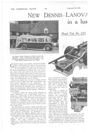
GREAT interest was aroused, during the Scottish Show, in November last, when it was ,announced that an oil engine of the Lanova, low-pressure type was to be standardized as a power unit for certain of the chassis manufactured by Dennis Bros., Ltd. Since then much work and research has been devoted to improving the original design, with the result that many alterations of an important nature have been made, and in its latest form the unit is very different from that which was exhibited last year at Glasgow.
We recently carried out a test of a Dennis Lancet 32-seater coach in which this engine was installed, and were greatly impressed by its performance. To summarize the opinions we formed of the power unit before describing its behaviour and construction in detail, the characteristic which struck us as most outstanding is its remarkably smooth running. Vibration is almost absent.
A passenger within the saloon, unless possessed of expert information and well-developed powers of observation, would hardly be able to detect the nature of the prime-mover. The noise does not pentrate into the body to a marked extent. There is what might be described as a rhythmical throb, rising and falling in intensity with movement of the accelerator pedal,and not wholly unlike that audible in the forward coaches of an express train.
The smell from the exhaust. is barely noticeable, and during the entire test we observed no smoke, except the merest puff immediately after starting up from cold. This operation, incidentally, was performed in our presence without the slightest difficulty, after the preheating plugs had been switched on for about 15 seconds.
In respect of power output, this seems more than ample for coach or bus operation, even in hilly districts. The engine, however, is governed to 1,800 r.p.m. Thus with the 5-to-1 axle ratio and fourspeed gearbox used in the Lancet chassis, the maximum
speed is limited to 41 m.p.h. There may be coach operators who hold the opinion that a higher maximum road speed than this is desirable, but there is no question that a good average can easily be maintained.
We made a number of entirely successful stop-andrestart tests on a l-in-7i gradient and subsequently observed an ascent of Hindhead Hill on the main London Portsmouth Road. This three-mile climb was accomplished in third and fourth gears at over 20 m.p.h. and for the major part of the distance with power in hand. Top gear was eAgaged about half a mile before the summit was reached and the coolingwater temperature immediately afterwards was 165 degrees F. The time for the three miles was 8 mins. 20 secs., which gives an average speed of 21.6 m.p.h.
Our consumption test, which consisted of a run from the Guildford By-pass to Cobham and back, produced a return of 17.5 m.p.g., which is equivalent to over 135
gross ton-m.p.g. The latter figure is higher than that for a 7-ton goods oiler, averaged from past road tests we have conducted, whilst the former is about the same as that obtained from another 32-seater equipped with a first-class oil engine that has passed through our hands and more than double the m.p.g. of a comparable petrol coach.
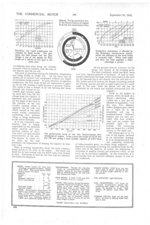
In connection with the accompanying acceleration and braking graphs, the former shows good liveliness and flexibility when it is remembered that only a four-speed box is used, whilst in considering the latter, allowance must be made for the fact that the tested chassis was over a year old, that the degree of vacuum available is controllable, and that, in view of the fact that our test was primarily of the power unit, no care had been taken to verify that the brakes were properly adjusted, etc. Furthermore, a test of an identical chassis (with a petrol engine) was. reported in The Commercial Motor dated
January 19, 1932, and the brake-test results included. Mention should also be made of the apparent underloading of the coach. Only one ton of weights was carried, which is not the equivalent of 32 persons. This was done to compensate for the unusually heavy body.
The total of 3 tons 15 cwt. was considered to be a representative figure for a typical body with a full complement
of passengers.
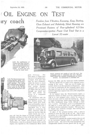
In its original form the Dennis-Lanova engine, a distinctive feature of which is its low compression-ratio (12i to 1), was equipped with a device by means of which the ratio could be raised for starting up. This is no longer incorporated, heater plugs being used. These are Beru, double-pole plugs, wired, through a resist ance, in series. Incidentally, each is accommodated in the had in a recess with only a small aperture con necting it with the combustion chamber. This passage is so shaped and relatively arranged that burning fuel cannot enter the recess.
In place of the pressure-varying valve, a plug is
inserted to form the back of the air cell. This is held in position by a short slightly flexible girder-like piece, itself secured by two studs.
Diametrically opposite the venturi-mouth of the air cell
is the horizontal injector which is provided with a guarded nozzle. The roof of the head incorporates two straight-sided circular recesses placed side by side and
overlapping each other along the cylinder diameter which is common with the axis of the injector and the air cell.
The cycle of operations during the induction, compression It is this controlled ccmbustion that is largely responsible for the relatively silent running and comparative absence of vibration which are such marked characteristics of the unit. The manner in which tha minimizes the importance of keeping. the injector in firstrate order.
There is nothing unorthodox about the main constructional points of the body of the engine. The block and trunk are an iron casting with the heads (also iron) formed in pairs. Aluminium is used for the base and wet nitridediron liners are employed.
Of the greatest interest, however, are the design and layout of the working parts. The steel crankshaft, which has 31-in, main and big-end journals is hardened. It runs in steelhacked white-metal bearings, whilst white metal is also used for the big-ends but is run directly into the rods and ca: s. The former are of II section, the flanges continuing around the bearing, and are not split at right angles but at a small angle to the axis. .Thus the piston and rod can be assembled on the bench and inserted downwards into the
cylinder.
While on the subject of pistons, these are made of a
silicon aluminium alloy (which has a very low coefficient of expansion), five flat tops, 2-in, diameter hollow gudgeon pins (which are a tight fit iii the aluminium and run in hardened-bronze little-end bushes) and are each provided with four pressure rings and one scraper ring situated right at the bottom. The connecting rods are forged for a drilled oil-way to the small end.
The timing gear is at t'-e rear of the engine, enclosed in an aluminium housing. It is of straightforward lay
out, consisting exclusively of helical-toothed gears, no chains being employed.
important advantage of driving the auxiliaries from the flywheel end of the shaft is, Of course, the elimination of variations in angular velocity per revolution which, at the front, are by no means negligible. In this connection, it is noteworthy that no torsional vibration damper is used on the crankshaft. The camshaft operates push-rods and straightforward rocker gear, the valves being arranged vertically and in line with the head. There are ball-ended adjusters on the push-rod ends of the rockers and hardened rollers on the valve ends.
A C.A.V.-Bosch injection pump, incorporating a governer of the same make, is driven in tandem with the Dennis exhauster. This is a simple gear-type device fed with oil under pressure and capable—as was demonstrated to us—of raising a 24-in, vacuum at ticking-over speed in a minute or so. An important detail is that the torque to the driven rotor is imparted by a shearable key.
The second stage of the governing motion is regulated by a device between the ball-governor and the doublehelix advance and retard mechanism. It incorporates a cam-shaped slot, forming one arm of a hell-crank, in which the roller-end of the ball-governor lever works. This arrangement allows the designer to impart, by varying the cam contour, the ideal movement throughout the speed range of tho engine, to the actual sliding sleeve on
the injection-pump-drive shafts. For sheer mechanical ingenuity, this device must evoke the greatest admiration. There is one more point that deserves inclusion in this list of interesting engine features. The whole discharge from the water pump is directed to the centre points of the cylinder heads, so that the maximum amount of heat (which is the same in the case of each cylinder), is extracted from the hottest part and distortion is thus prevented. The cooling water is also drawn from the head, that in the cylinder jackets circulating locally merely by the thermo-syphon principle.
The care that has been devoted to this engine has had as its object, primarily, efficiency in respect of performance and durability, and, secondly, economical production. The outcome is a power unit that should satisfy the most exacting user and that can be offered at a far from formidable price. We hold the view that it is a fit bearer of the name it carries.