


Unappreciated Jacking Loads
Page 49
If you've noticed an error in this article please click here to report it so we can fix it.
The Position of the Jack and the Side Thrust May Increase the Load by as Much as zoo per cent.
By FRANK R. CARR
(Accessories Manager, Dunlop Rutter Co., Ltd.) NAOST jack failures can be traced to Ilfloverloading, but this is more often than not due to a lack of appreciation on the part of the user of the actual weight a jack is called upon to lift. It is generally believed that a jack has to lift only a quarter of the total weight of a vehicle—for instance, a 2-ton jack is assumed to be satisfactory for raising one wheel of a vehicle weighing 8 tons.
Such, however, is not the case. The weight on the jack largely depends on the position in which it is placed under the axle. The nearer it is to the middle the heavier will be the load.
Let us assume that the 8-ton vehicle has its load so evenly distributed that each tyre supports 2 tons. If the jack could be placed in the centre of the tread of one tyre, the load in the initial stages of its lift would approximate to 2 tons. If it be positioned under exactly the centre of the front or back axle, it would have to lift approximately 4 tons.
, As, however, it is customary to put the jack under the spring, which is between the tyre and the middle of the axle, it follows that it will always be called upon to lift more than the weight being borne by the wheel. The amount of increase depends upon a number of factors, which include the relation of the jacking point to the centre of the tyre tread and the centre of the axle, the distribution of the load over the front and back axles, and over the near and the off side of the vehicle (depending upon the type of body, the packing of the load and the road camber), the rigidity of the chassis frame, and the height of lift required.
Thus, it is obviously impossible to lay down any hard and fast rules, as the factors vary with every vehicle, but the following tests, carried out on an A.E.C. Q-type coach, specially laden, should be of interest.
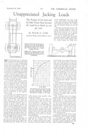
The total weight of the vehicle was 7 tons 8k cwt., whilst the front and rear axle weights were 3 tons 6 cwt., and 4 tons 2i cwt., respectively. The coach was driven to a weighbridge ard so positioned that only the near-side front wheel was on the bridge, but placed in such a manner that a jack could correctly be located on the weighbridge to permit the load upon it being weighed at various stages of the lift. The arrangement is shown in an accompanying diagram.
It is of interest to record that the weight of this near-side front corner with the tyre inflated was 1 ton 81 cwt., whereas after the tyre (40-in. by 8-in.). had been deflated, the load
on the weighbridge was only 1 ton 4 cwt. The reason the near-side wheel weight did not represent half the front axle weight was because the driver's cab was mounted forward on the off side.
The jack, having been placed in its correct operating position under the spring, was then raised one inch at a time and the load on it at various stages of lift recorded. The results are shown in the accompanying graph.
It will be noticed that the weight increased somewhat rapidly during the first three inches of lift, during which the vehicle spring was being ccm pressed back to its normal laden position. At the point when the tyre was just clear of the ground, the jack was bearing a load equivalent to two-thirds of the total axle weight, but this increased as the jack was raised until the load was double the wheel weight.
As a jack is extended other forces conic into operation, as it is not constantly at right angles to the axle. The higher a jack is raised the more side strain is thrown on the ram or screw because the head is prevented from travelling in a truly vertical direction. An accompanying diagram illustrates this y oint.
It has been proved that a jack with a convex base or one mounted on a trunnion, to permit of it tilting as the angle of the axle alters during the lift, is much easier to work, thereby implying that considerable side-thrust OCOEE with the conventional type. Unfortunately, such tilting jacks are liable to slip out of position when used on smooth surfaces.
With hydraulic jacks, oil is simply pumped under the ram and a relatively small amount of effort builds up sufficient pressure to raise heavy loads. Friction losses in hydraulic jacks are lcw due to the absence of gears, bearings and screws, which require greatly increased effort to operate as the load becomes greater. The ease with which hydraulic jacks work is apt to be taken as an indication that the load being raised is well within the capacity of the particular jack.
A ccnsideration of the whole of the foregoing facts indicates the necessity of choosing a jack of ample capacity, i.e., one capable of raising at least two-thirds the weight of the, heavier axle load. Only by doing this can one expect satisfactory jacking service.