


PATENTS SUMMARIZED.
Page 24
If you've noticed an error in this article please click here to report it so we can fix it.
A Sphinx Paraffin Vaporizer.
A paraffin heater which is situated within the combustion space itself, should certainly not have the objection that it does not get enough heat, whatever other failing it might prove to possess. This is the distinguishing feature of a device which has been patented by the Sphinx manufacturing Co., of 240 242, Bradford Street, Birmingham. .
This concern is a well-known maker of sparking plugs, asid the vaporizer is very similar to that very essential. component of the internal-combustion engine. Within a hollow screwed plug, resembling in form the body of a sparking plug, is a coil of tubing. This coil enters and emerges from the plug through holes conveniently situated in the screwed gland-nut of.the plug; JIG terminals take the form of union coop
lings, and the tubing is brazed in position in the nut of the plug, thus obviating any possibility of leakage at those points. The specification is numbered 108,224.
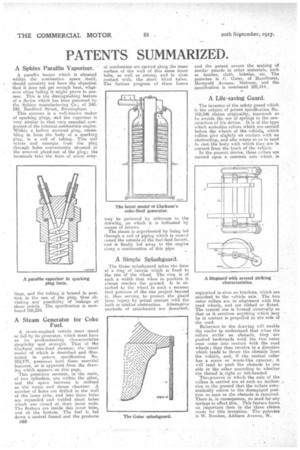
A Steam Generator for Coke Fuel.
A steam-engiried vehicle must stand or fall by its generator, which must have as its predominating characteristics simplicity and strength. That of Ole Clarkson coke-fired steamer, the latest model of which is described and illustrated in patent specification No. 108,177, possesses both these essential features, as is apparent from the drawing which appears on this page.
This generator consists, in the main, of two cylinders, one within the other, and the space between is utilized as the water and steam chamber. A number of holes are drilled in the wall of the inner tithe, and into these holes are expanded and Welded short tubes which are -closed at their inner ends. The firebars are inside this inner tube, and at the bottom. The fuel is fed down a central funnel and the products
C62 of combustion are carried along the inner surface of the wall of this same inner tube, as well as among, and in close contact with, the short blind tubes. The further progress of these fumes may be gathered by reference to the drawing, on which it is indicated by means of arrows. .
The steam is superheated by being led through a coil of piping which is wound round the outside of the fuel-feed funnel, -and is finally led away to the engine along a continuation of this pipe.
A •Simple Splashguard.
The Guise splashguard takes the form of a ring of canvas which is fixed• to the rim of the wheel. The ring is of such a width that when in position it almost reaches the ground. It is attached to the wheel in such a manner that portions of the rim project beyond it, thus serving to protect the guard from injuryby actual contact with the kerb or similar obstruction. Alternative methods of attachment are described, and the patent covers the making of similar guards in other materials, such as leather, cloth, bristles, etc. The patentee is C. Guise, of Hazelhurst, Hornyold Avenue, Malvern, and the specification is numbered 108,414. ,
A Life-saving Guard.
The inventor of the safety guard which is the subject of patent specification No. 108,346 claims originality, inasmuch as he .avoids the use of springs in the construction of his device. It is of the type svhich embodies rollers which are carried before the wheels of the vehicle., which rollers give slightly on contact with an obstruction, and also rotate so as to tend to cast the body with which they are in contact from the track of the vehicle.
In the present device, three rollers are carried upon a common axle which. is supported in slots on brackets, which are attached to the vehicle axle. The two outer rollers are in alignment with the road wheels, and are ribbed or fluted. The central one is formed externally so that as it revolves anything which may be in contact is propelled to the side of the road.
Reference to the drawing will enable the reader to understand that when the rollers strike an obstacle, they are pushed backwards until the two outer ones come into contact with the road wheels; they then revolve in a direction which tends to throw the obstacle from the vehicle, and, if the central roller has a screw or worm-like exterior, it will tend to push the obstacle to one side or the other according to whether the thread is right or left-handed.
The, grooves in which the axle of the rollers is carried are at such an inclination to the ground that the rollers automatically return to the disengaged position so soon as the obstacle is removed. There is, in consequence, no need for any springs to effect this.. This feature forms an important item in the three claims. made for this invention. The patentee is W. Brookes, Addison Avenue, W. .