


Frictional Steering-gear Stabilizer
Page 36
If you've noticed an error in this article please click here to report it so we can fix it.
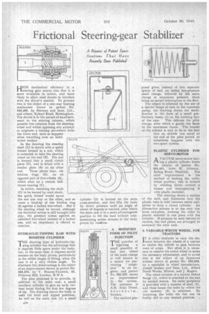
HIGH mechanical efficiency in a !steering gear means also that it is more reversible in action, and more likely to allow road shocks to interfere with the driver's control. To prevent this is the object of a one-way braking mechanism shown in patent No. 563,489, by Burman and Sons, Ltd., and others, Ryland Road, Birmingham. The device is in the nature of an-attachment to the steering column, which permits free rotation from the steeringwheel end whilst opposing any attempt to originate a turning movement from the lower end, such as happens when travelling over an indifferent surface
In the drawing the steering shaft (1) is shown with a quick thread housed in a nut, which is extended to take the steering wheel on the end (2). The nut is formed into a small clutch plate (3), and is fitted with a similar plate (4) on its other end. These plates bear, via friction rings (5), on an opposed pair of free-wheels (6), which abut on a central ballthrust bearing (7).
In action, assuming the shaft (1) to be turned by road shock, the quick thread would move the nut one way or the other, and so cause a bind-Up of one friction ring (5) against a locked free-wheel. But if the steering wheel be turned, although the frictional action is still brought into play, the pressure comes against an unlocked free-wheel instead of a locked one, and no impedance is offered to rotation.
HYDRAULIC-TIPPING RAM WITH BOOSTER CYLINDER
THE slanting 'type of hydraulic-tipI. ping cylinder has the advantage that it requires little space under the body, but, at the same time, it imposes severe stresses on the body pivots, particularly in the initial stages of lifting, when the ram is at a very obtuse angle. To eliminate this disadvantage is the object of an improvement shown in patent No. 563,576, by V. Bourne-Vanneck, 25, Primrose Hill, London, N.W.3.
The plan proposed is to provide, in addition to the main ram, a small auxiliary cylinder to give an early vertical boost during the first few degrees of tip. The drawing shows the body in both the level and tipped positions. As well as the main ram (1) a small cylinder (2) is located on the same cross-member, and this lifts the body by direct pressure until an angle of about 15 degrees is reached, after which the main ram is in a snore advantageous position to lift the load without communicating undue stresses to the body pivots by reaetion. posed gives, instead of two separate spurts of fuel, an initial low-pressure small charge, followed by the main charge at maximum pressure, there being no actual interruption in the flow.
The object is attained by the use of a special shape of cam in the injection pump; the drawing shows the modification in the form of a small preliminary hump (1) on the working face
of the cam. This delivers the pilot charge, after which a gentle rise leads to the maximum throw. The benefit of the scheme is said to lie in the fact that no dribble can occur at the end of the pilot period, as sometimes happens with the two-spurt system.
PLASTIC CYLINDER FOR SERVO-MOTOR
A VACUUM servo-motor hay
ing a plastic cylinder forms the subject of patent No. 563,401, from M. Johnson, Ealing Road, Wembley. The chief improvement is the method of making the cylindrical portion ; this is formed by winding fabric around a former and impregnating it with plastic material, The drawing shows a section of the unit, and illustrates how the plastic tube is held between metal endplates to form a closed cylinder. An alternative scheme is to use only one loose end-plate, forming the other in plastic material in one piece with the cylinder. If pressure be used instead of suction, the end plates are arranged to surround the tube ends.
A VARIABLE-WIDTH WHEEL FOR TRACTORS I T is often desirable to vary the dis tance between the wheels of a tractor • to enable the vehicle to pass between rows of crops. But often it is necessary to remove the entire wheel to make the necessary adjustment, and to avoid _ this is the object of an improved scheme shown in patent No. 563,508, by a specialist in wheel manufacture, Joseph Sankey and Sons, Ltd., Albert Street Works, Bilston, and J. Rogers.
The wheel consists of a central dished flange (1), which is attached to the hub .by normal means. Its outer periphery is provided with a number of slots (2), and these house the bolts by which the rim member (3) is attached. By loosening the bolts the rim can be bodily slid to any desired position..