


Full-torque Power Take-off for Standard Chassis
Page 44
If you've noticed an error in this article please click here to report it so we can fix it.
A Resume of Recently Published Patent Specifications
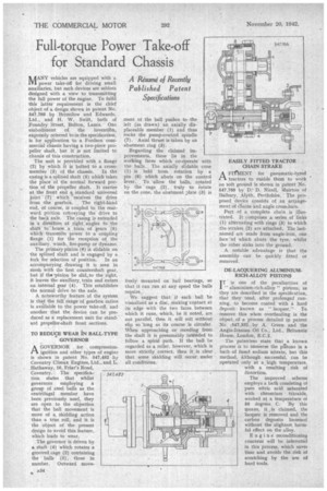
AANY vehicles are equipped with a LH power take-off for driving small auxiliaries, but such devices are seldom designed with a view to transmitting the full power of the engine. To fulfil this latter requirement is the chief object of a design shown in patent No. 597,766 by Bromilow and Edwards, Ltd., and H. W, Swift, both of Foundry Street, Bolton, Lancs. One embodiment of the inventiVin, expressly referred to in the specification, is for application to a Fordson cora: mercial chassis having a two-piece propeller shaft, but it is not limited to chassis of this construction.
The unit is provided with a flange (2) by which it is bolted to a cross
member (3)_ of the chassis. In the casing is a splined shaft (5) which takes the place of tire normal forward portion of the propeller shaft. It carries at the front end a •standard universal joint (7) .which 'receives the drive from the gearbox. The right-hand' end, of course, is coupled to the rearward portion cobveying the drive to the back axle. The casing is extended in a direction at right angles to the shaft to house a train of gears (3) which transmits power to a coupling flange (1) for the reception of the auxiliary, winch, fire-pump or dynamo.
The primary pinion (6) is slidable on the splined shaft and is engaged by a
fork for selection of position. In an accompanying drawing it is seen in mesh with the first countershaft gear, but if the.pinion be slid.to the right, it leaves the auxiliary, train and enters an internal gear (4). This establishes the normal drive to the axle.
A noteworthy feature of the system is that the full range of gearbox ratios is available to the power take-off, and another that the device can be pro. duced as a replacement unit for stand: ard propeller-shaft front sections.
TO REDUCE WEAR INT BALL-TYPE GOVERNOR A GOVERNOR . for compressionCIL ignition and other types of engine is shown in patent No. 597,482 by Coventry Climax Engines, Ltd., and L. Hathaway, 16, Friar's Road, Coventry, The specification states that whilst governors employing a group of steel balls as the centrifugal member have been previously used, they are open to the objection that the ball movement is more of a, skidding action than a true roll, and it is the 'object of the present design to avoid this feature, which leads to wear.
The governor is driven by a shaft (4) which rotates a grooved cage (2) containing the balls (5), three in number. Outward move merit of the ball pushes to-the left (as drawn) an axially displaceable member (1) and thus rocks the pump-control spindle (7). Axial thrust is taken by an abutment ring (3).
Regarding the claimed improvements, these lie in the working faces which co-Operate with the balls. The axially sliclable cone (1) is held from rotation by a pin (6) which abuts on the control lever. To allow the balls, rotated by the cage (2), truly to rotate on the cone, the abutment plate (3) is
freely mounted on ball bearings, so that it can run at any speed the balls require,
We suggest that if each ball be visualized as a disc, making coptact at its edge with the two faces between which it runs, which, be it noted, are not parallel, then it will roll without slip so long as its course is circular. When approaching or receding from the shaft it is presumably intended to follow a spiral path. If the ball be regarded as a roller, however, which is more strictly correct, then it is clear that some skidding will occur under all conditions. EASILY FITTED TRACTOR CHAIN STRAKE
AFIAIENT for pneumatic-tyred tractors to enable them to work on soft ground is shown in patent No.
547,768 by D. Nicoll, Muirtcm of Balhary, .Myth, Perthshire. The proposed device consists of an arrangement of Chains and angle cross-bars.
Part of a complete chain is Milstrated, It comprises a series of links (1). alternating with rings (8) to which the strakes (2) are attached, The lastnamed are made from angle-iron, one face of which abuts the tyre, whilst the other sinks into the ground.
A notable advantage is that the assembly can he quickly fitted or removed.
DE-LACQUERING ALUMINIUMRICH-ALLOY PISTONS I T is one of the peculiarities of " aluminium-rich-alloy " pistons, as they are described in the specification, that they tend, after prolonged running, to become coated with a hard deposit known as ." lacquer." To remove this when overhauling is the object., of a process detailed in patent No. -547,332. by A. Green and the Anglo-Iranian Oil Co., Ltd., Britannic Rouse, London, E.C.2.
The patentees state that a known process is to immerse the pistons in a bath of fused sodium nitrate, but this method, although successful, can be operated only at a , high temperature, with a resulting . risk of distortion.
The improved scheme employs a bath consisting oi pure nitric acid saturated with chromium trioxide, worked at a temperature oi 50 degrees C. By this means, it ,is claimed, the lacquer is removed and the carbon deposits loosened without the slightest, harmful effect on the alloy.
Engine reconditioning concerns will be interested in this 'process, which saves time and avoids the risk of scratching by the use of hard tools.