


A NEW. ROTARY VALVE ENGINE.
Page 40
If you've noticed an error in this article please click here to report it so we can fix it.
A Résumé of Recently Published Patent Specifications.
MANY attempts have been made to popularize the rotary valve, both In automobile engines and in stationary internal-combustion 'engines,' extending over a great many years, but up to the present but little headway aupears to have been made. In the case of patent No. 298,687, the well-known name of F. W. Lanchester asipears, coupled with that of the Daimler Co., Ltd.
In this design the cylinder is provided with a sleeve which is capable of a slight sliding movement, only sufficient to permit it to press upwards ,sufficiently to form a gas-tight seal with the revolving valve. Two sliding plungers with • angular ends and springs pressing' them inwards, hold the sleeve against the rota ling valve while there is no pressure in the cylinder, but on the compression and firing strokes the sleeve is forced upwards by the internal pressure in the cylinder, thus helping to prevent the escape of gas between he upper end of the sleeve and the rotary valve.
The, spark plug is situated in a place in the sleeve which is threaded for its reception, but passes through an opening in the outer cylinder which is large enough to permit the necessary slight movement Of the sleeve. Ths rotary valve is provided with a passage which enables it to form a communication with the cylinder and the exhaust and inlet ports in the order of the cycle.
A small port is provided in some cases, which allows the passage in the valve to communicate with the atmosphere for a brief period as it revolves—the exact function of this port is not made very clear in the drawings or in the text. The valve is, of course, rotated by means of gearing, so that its movement is always
synchronized with that of the piston as in other four-stroke engines. No mention is made of any special mans for lubricating the rotary valve, nor is any method mentioned by which the scoring of the surfaces of the valve and its mating surfaces can be avoided. To maintain a gas-tight seal, such faces naust work under a very considerable pressure during movement. The difficulty of retaining a film of lubricant under such conditions has been the cause, in previous efforts to employ such valves, of scoring and the consequent leakage of gas.
B44
A Spring. which can Vary its Effective Length.
AN arrangement whereby springs can take up various working lengths is described in specification No. 280,243, by G. H. Schieferstein, Of Charlottenburg. In this arrangement, controlling mem:hers are placed above and below the
spring, so that its effective length is shortened as it departs from its original. forth.. The exact object aimed at is not made plain in the specification, but we surmise that the prevention of a distinct period of vibration is aimed at; troth in the bending and in the rebound.: The spring itself is described as being of one substance all along ita length, instead of having plates of various lengths as is usually'found in spring design, The spring when free has a certain given curve, but as it is depressed, it gradually increases its length of bearing on the member which is above it, thus producing the effect of shortening the length of the spring. A member of more acute curve than the spring is placed below the latter,,so that on the rebound, an action similar to that described above can take place. With regard to the member placed above the spring, we have surely seen efforts made in this direction in this country.
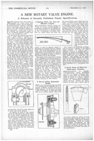
A Direct-acting Hydraulic Brake.
THE form of hydraulic brake described
in specification No.-X18,857, by O. L. Skopik, of Berlin, contains some interesting features. In the hub is mounted a ring of T-section, of which the radial web is the surface against which bear the non-revolving faees which form the brake. In what may be called the back Plate, there is an annulus; which forms a hydraulic cylinder into which fluid can be forced under pressure. The two braking surfaces are brought to bear on the T-shaped. ring so, that they do ,net exert any end pressure on the bearings of the 'hub, the parts which may be described as the annular cylinder and Piston being so arranged, that their action,. and. reaction ..balance, the pressure
exerted. against the
web Of -the T-shaped TI ng attached to the • hub. . • .
Felt washers are mentioned as, being used to prevent a leakage of. the fluid-under pssatire. We --can see some difficulty, however, in holding such a pressure as would ,be necessary for the efficient application of a brake, unless some better seal were stied:than' felt washers.. The' wording of the speedffeation is needlessly elaborate in. details' that do not matter, but is not very plain in the more importent.features of . the invesitionsorm part. of the apparatus .being described as a "ring-shaped ring disc."
A Novel Form of Plate for Multi-plate Clutches.
SPECIFICATION No. 284,268,
KirchbachSche Work, Kirchbach and Co., of Caswig, Germany, describes a novel form of clutch plate which is formed of a fibrous material which is soaked in a binding medium, capable of withstanding mechanical stress and heat. During the manufacture of such rings a metal edge is introduced which, by means of serrations and holes, is firmly united to the fibrous material. This ring is provided with interruptions which can engage with mating interruptions on the inside of the outer clutch member. The particular advantage claimed for the construction is not made very plain in the specification.