


DENNIS'S INVADE THE ONE-TON MARKET.
Page 8
Page 9
If you've noticed an error in this article please click here to report it so we can fix it.
Neatly pesigned 20-25-cwt. Chassis at a Competitive Price. Unit-constructed Engine, Clutch and Gear-box, and Duplex Rear-wheel Brakes.
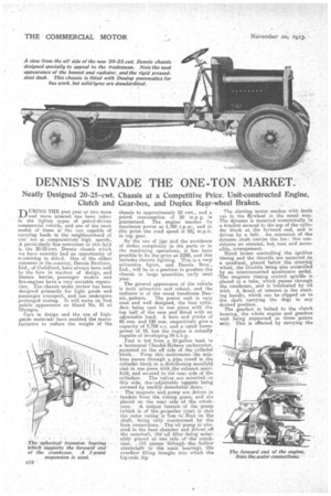
-r-1 MING THE past year or two more J_JP and more interest has been taken in the lighter types of petrol-driven commercial vehicle, and one of the most useful of these is the van capable of carrying loads in the neighbourhood of one ton at comparatively high speeds. A particularly fine newcomer in this field is the 20-25-cwt. Dennis chassis which we have recently had an opportunity of ir.amining in detail. One of the oldest conoernS in the country, Dennis Brothers, Ltd., of Guildford, have always been well to the fore in matters of design, and Dennis lorries, passenger models and fire-engines have a very enviable reputaI ion: The chassis under review has been designed primarily .for light goods and passenger transport, and has undergone prolonged testing. It will make its 'first public appearance on Stand No. 91 at Olympia.
Cara in design and the use of highgrade materials have enabled the _manufacturers to reduce the weight of the chassis to approximately 23 cwt., and a petrol consumption of 20 m.p g. is guaranteed. The engine reaches its maximum power at 1,765 r.p.m., and at this point the road speed is 25A m.p.h. in top gear.
By the use of jigs and the avoidance of undue complexity in the parts or in the machining operation's, it has been possible to fix the price at £295, and this includes electric lighting. This is a very attractive figure, and Dennis Bros-, Ltd., will be in a position to produce the chassis in large • quantities_ early next year.
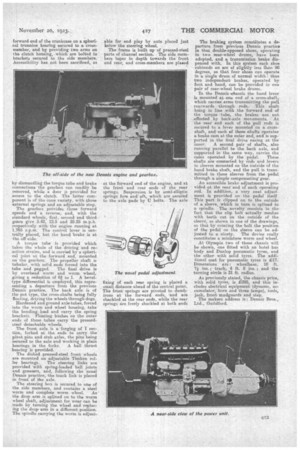
. The general appearance Of the vehicle is both attractive and robust, and the radiator is of the usual handsome Den nis, pattern. The power unit is very neat and well designed, the four cylinders being cast in one piece with the top half of the case and fitted with an adjustable head. A bore and stroke of 85 mm. and 120 mm. respectively give a capacity of 2,724 c.c. and a rated horsepower of 18, bat the engine is actually capable of developing 34 b.hp.
Fuel is fed from a 10-gallon tank fo a horizontal Cloudel7Hobson 'carburetter, . mounted on the off side..of _Um -cylindet 111-ok. From this-iriStrnmentr the mixpasses thiviugh pipecored in the Cylinder bloek.te aLdistrihuting_rnanifold cast in one piece With the exhaust Mani.-: fold; :and "secured to the near tide .01 the . cylinders. The 'valves are _mounted Dii . this side, the .iadjUStable . tappets.: _being covered by yeadily.detachable,deors...` , The magneto and, pump are driven in tandem from the timing gears,' andeTC placed on the near 'aideof tlie case.A unique feature of the pinup (which is of the .propeller type) is that the outer casing is free to float onthe shaft, 'being only Onaistra.iried .by the hOse connections. The` Oilpuny issitn ated • in the limo chaMber and 'driven off the camshaft, th-egil filler .-being 'acOeSsibly placed at him 'aide, Of' the crankcase. -Oil passes--ilif:fiugh
the hollow crankshaft to the main' bearirie, the .overflow filling troughs into which the Lig-ends .di
The starting motor meshes with teeth cut in the flywheel in the usual way. The dynamo is mounted eccentrically ut a bracket secured to tie top of the cylinder block at the forward end, and is driven by a belt. An extension of the dynamo shaft carries the fan: this eonstitutes an unusual, but neat and accessible, arrangement.
Hand levers controlling the ignition timing and the throttle are mounted on a quadrant, placed below the steering wheel, the throttle bting also controlled by an interconnected accelerator pedal. "The magneto timing control spindle is placed in a tube, which passes through the crankcase, and is lubricated by oil mist_ A 'detail of interest is the starting handle, which can be clipped on to the diva carrying the clogs in any desired position. The gearbox is bolted to the clutch housing, the whole engine and gearbox unit being supported at. three points only. This is effected by carrying the forward end of the crankcase on a spherical trunnion bearing secured to a crossmember, and by providing two arms on the clutch housing, which are bolted to brackets secured to the side members. Accessibility has not been sacrificed, as by dismantling the torque tube and brake connections the gearbox can readily be removed, while a door is provided for access to the clutch. The latter component is of the cone variety, with three external springs and an adjustable stop. The gearbox provides three forward speeds and a reverse, and, with the standard wheels, first, second and third gears give 5,42, 12,5 and 25.25 m.p.h. respectively with the engine running at 1,765 r.p.m. The control lever is centrelly placed, but the hand brake is at the off eide.
A torque tube is provided which takes the whole of the driving and reaction strains, and is carried by a spherical joint at the forward end, mounted on the gearbox. The propeller shaft is tubular, with solid ends forced into the tube and pegged. The final drive is by overhead worm and worm, wheel, giving a reduction of 6,1. to 1. A beveltype differential is employed, this representing a departure from the previous Dennis practice. The back axle is of the pot type, the cross-shafts being fully floating, driying the wheels through dogs.
Hardened and ground axle tubas, forced into the worm and wheel housing, take' the bending load and carry the spring brackets. Floating bushes on the outer ends of these tubes carry the pressedsteel detachable wheels.
The front axle is aforging of I seclien, forked at the ends to carry the pivot pins and stub axles, the pins being secured to the axle and -working in plain
bearings in the forks. A ball thrust bearing is provided. The dished .pressed-steel front wheels are mounted on adjustable Tiniken rol ler bearings. The steering links are provided with spring-loaded ball joints and greasers, and, following the usual Dennis practice, the track link is placed in front of the axle.
The steering box is secured to one of the side members, and contains a steel worm and complete worm Wheel. As the drop arm is spline(' on to the worm wheel shaft, adjustment for wear can be made by turning the wheel and replae. Mg the drop arm in a different position. The spindle carrying the worm is adjust
able for end play by nuts placed just below the steering wheel.
The frame is built up of pressed-steel parts of channel section. The side members taper in depth towards the front and rear, and cross-members are plaited at the forward end of the engine, and at, the front and rear ends of the rear springs. Suspension, is by semi-elliptic springs fore and aft, which are secured to the axle pads by Ti bolts. The axle fixing of each rear spring is placed a small distance ahead of the central point. The front springs are pivoted to dumbirons at the forward ends, -and are shackled at the rear ends, while the rear springs a;re freely shackled at both ends The braking system constitutes a departure from previous Dennis practice in that double-opposed shoes, operating in two. rear-wheel drums, have been adopted, and a transmission brake dis pensed with. In this system each shoe subtends an are of slightly less than 90 degrees, so that four shoes can operate in a single drum of normal width: thus two independent, brakes, operated by foot and hand, can be provided in one pair of rear-wheel brake drums.
In the Dennis 'chassis the band lever is mounted at one end of a cross-shaft, which carries arms transmitting the pull rearwards through rods. This shaft being in line with the forward end of the torque tube, the brakes are not affected by ba;ck-e,xle movements. At the rear end each of the pull rods is secured to a lever mounted on a cross shaft, and each ef these shafts operates a brake cam at the outer end, and is sup ported in the final drive casing at the inner. A second pair of shafts, also running parallel to the back axle, and supported in the same way, carries the cams operated by the pedal. These shafts are connected by rods and levers to sleeves mounted on the outside of the. hand brake shaft, and the pull is transmitted to these sleeves from the pedal through a simple compensating gear.
An accessible brake adjustment is provided -at the rear end of each operating rod. In addition, a very neatadjustment is provided on the pedal' itself,
This part is clipped on to the outside of a sleeve, which in turn is splined to a spindle. The novelty consists in the fact that the clip bolt actually meshes with teeth cut on the outside of the sleeve, as shown in one of the drawings, so that by rotating the bolt the position of the pedal on the sleeve can be ad justed to a nicety. The device really constitutes a miniature worm and wheel. At Olympia two of these chassis will be shown, one fitted with an hotel bus body and Dunlop pneumatic tyres, and the other with solid tyres. The additional cost for pneumatic tyres is £17. Dimensions are: wheelbase, 10 ft. 7i ins. ; track, 4 ft. 8 ins.; and the turning circle is 31 ft. radius.
As previously stated, the chassis price, with solid tyres, is £295, and this in
cludes electrical equipment (dynamo, accumulator, horn and three lamps), tools, jack, front mudguards and step.
The makers address is : Dennis Bros., Ltd., Guildford.