


A TWO-STROKE SWASH-PLATE ENGINE.
Page 56
If you've noticed an error in this article please click here to report it so we can fix it.
A Resume of Recently Published Patents.
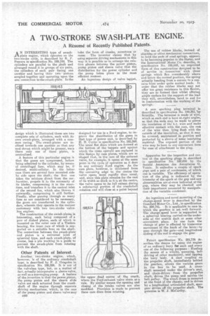
A N INTERESTING type of awashplate engine, which operates on the two-stroke cy'cle, is described by R. P. Pescara in specification No. 189,145. The cylinders are parallel to the shaft and arranged round it in groups of six pairs, the cylinders of each pair facing one another and having their two pistons coupled together and operating upon the one connection to the swaeh-plate. In the
design which is illustrated there are two complete sets of cylinders, each with its own awash-plate, arranged with a common casing_ Te swa,sh-plates are inclined towards one another so that any 'end thrust which might be present, were there only one of these plates, is neutralized.
A feature of this particular engine is that the gases are compressed, before being admitted to the cylinder, by means of centrifugal fans, which may be, if desired, multi-cellular. In the latter case there are several fans mounted side by side upon the shaft ; the first one takes the mixture direct from the car
burettes, propels it to the extremity of its blades, compressing it in the meantime, and transfers it to the central, inlet of the second fan, which also throws it outwardly, compressing it still further. Finally, after passing through as many fans as are considered to be necessary, the gases are transferred to the cylinders, wherein they operate in the manner customary with two two-stroke valveless engines.
The construction of the swash-plates is interesting, each being composed of a pair of dished plates, each of which is mounted on the outer race of a Timken bearing, the inner race of which is supported on a suitable boss on the shaft. The connection between the swash-plate and piston is a universal joint of spherical type, and each awash plate, of course, has a pin working in a guide to prevent the awash-plate from rotating with the shaft.
Other Patents of Interest.
Another two-stroke engine, which, however, is of the ordinary crankshaft type, is described by P. J. Gregoire in specification No. 198,324. It is not of the valveless type, but, as a matter of fact, actually incorporates a sleeve valve, as well as a scavenging pump. A feature of the invention is that the power piston, the pump piston and the sleeve slide valve are each actuated from the crankshaft of the engine through separate driving mechanisms, which, in the case of the pump piston and sleeve valve may C60 take the form of cranks, eccentrics or cams. The inventor claims that by using separate driving mechanisms in this way it is possible so to arrange the relative phases between the power piston, pump piston and sleeve valve that the distribution fur the power cylinder and the pump takes place in the most efficient manner.
An ingenious design of valve tappet, designed for use in a Ford engine, to in prove the distribution of the gases in that type of power unit, is described by H. H. Cutler in specification No. 192,360. The usual flat discs which are formed at the bottom of the tappets and against which the cams operate are replaced in this design by cam plates, which are so 'shaped that., in the case of the exhaust valve, for example, it. opens at the same point in the cycle of operation as it does in any ordinary Ford engine. As the cam plate, however, is thickened from the soncoming edge to the centre the valve opens more rapidly than usual, and, since this plate remains for the rest of its width as thick as it is at the. centre, the valve opens to its full extent during a substantial portion of the crankshaft rotation and will close at a point beyond the upper dead centre of the crank, svhere the Ford exhaust valve shuts as a rule. By similar means the opening and closing of the intake valves are also modified. Provision is made to prevent these cam-discs froin rotating. The use of rubber blocks, instead of shackles or other mechanical connections, to hold the ends of road springs, appears. tobe becoming popular in the States, and the International Motor Co. describe, in specification No. 198,653, an improved form of this construction designed to be of service in Connection' with those springs which flex eonsiderably above and below the normal position, the spring actually bending from a convex to a concave form under quite normal loads. In order that the rubber blocks may not offer too great resistance to this flexion, they are so formed that whilst offering ample surface for the support of the load they will, nevertheless, bend to and fro in conformation with the working of the springs.
A new sparking plug terminal is 'described in specification No. 199,361:by Scintilla. The terminal is made of wire. which at each end is bent at.right angles, so that the ends may be made to pierce the insulation of the h.t. wire and make effective contact with the core, the rest, of the wire then lying flush with the outside of the insulation, so that it may be covered, maintained in position and protected by a sleeve of some insulating material. The exposed portion of the wire may be bent to any convenient form for ease of attachment to the plug.
Apparatus for the inspection and control of the sparking plugs is described in specification No. 182,-816 by the Societe Anonyme des Aeroplanes G. Voisin. It embodies a couple of spark gaps and a pair of condensers, of which one is variable. The efficiency of operation of the plug is indicated by the intensity of the spark at the gap and any abnormalities are at once indicated at the gap, where they may be checked and their importance measured by manipulation of the variable condenser.
An ingenious and novel mounting of the change-speed lever is described by the Standard Motor Co., Ltd., in specification No. 204,741. It is applicable to cars in, which the gearbox is set well forward_ The change-speed lever is' supported in a spherical bearing carried on-the underside of the scuttle dash or some other convenient place. In one form the change of gear is effected by transverse movement of the knob of the lever—to pass through the gate—and longitudinal sliding of the rod to engage the gear.
Patent specification No. 201,736 describes the Means for using the engine of an ordinary lorry for each and every one of the following purposes : Hauling (by means of a winch), pumping, belt driving of other machinery, and tipping the lorry body. A claw coupling on the propeller shaft, immediately behind the gearbox, allows the various gears in the box to be used. A crossshaft mounted under the driver's seat, and chain-driven from the propeller shaft, drives the pump and carries the belt pulley. The winch drum is mounted at the front of the chassis; end is driven by a longitudinal articulated shaft, spurgear driven off the propeller shaft. The patentee is W. J. McCarthy.