


THE MAINTENANCE OF BRAKES,
Page 55
If you've noticed an error in this article please click here to report it so we can fix it.
Useful Hints from Our Driver and Mechanic Readers.
AN EXPRESSION of opinion concerning brakes comes Ito us in a letter from " A.J.F.," of Brighton. He tells us that he ha-s had, in all, 20 years' . experience of motor vehicles of all kinds,. in the course of which he has had to deal with not a few breakdowns resulting from brake failure. In the majority of cases, he states, these failures may be traced to one or othes of two principal causes. Either the retaining nut on the end of the rear axle has stripped, as the result of constant hammering by a wheel for which to much clearance has been provided, or as the result of the breakage of a differential shaft and consequent sideways movement of the wheel, away from the chassis.
In each case the driver receives no warning of the trouble, and the first thing that he knows is, either that the vehicle hegirs to run away---this happens when it is going down-hill—or that it comes to a. sudden stop, with engine and gears racing merrily round—that is, of course, if he is lucky and the wheel does not come right off.
'Of the two classes of failure named, that which involves breakage of the differential shaft causes most trouble, since it deprives the -driver of a vehicle equipped with a transmission brake; or, again, even where there is no transmission brake, it eliminates the possibility of • saving a smash by using the engine as a brake.
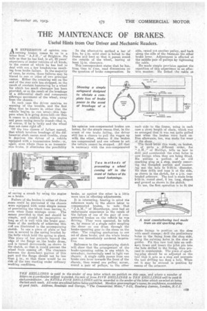
Failure of the brakes in either of these wiases could be prevented if the chassis were equipped with some simple means of preventing the wheel from leaving it, even when these mishaps occur. The means provided to that end should be simple, and should be inoperative so long as all ia well with the brake gear. Some of the methods of achieving this end are illustrated in the accompanying sketch. In one a piece of plate or bar iron is secured to the spring bracket by the bolts which hold the spring in place. This piece of bar projects beyond the edge of the flange on ,the brake drum, and is turned downwards, as shown in the sketch, so that it would prevent the wheel from coming off. The clearance between the down-bent portion of 'this part and the flange should not be less than 4 in., so that there would be no risk of the two meeting under ordinary working conditions.
In the alternative method a bar of 2-in, by mild steel is bolted to the frame and bent so that it passes round the outside of the wheel, leaving at least 11-in. clearance.
This correspondent states that he has, from time to time, read discussions on the question of brake compensation. hi
his opinion non-compensated brakes are better, for the simple reason that, in the event of one brake failing, the driver still has a chance to pull the wagon up with the other, whereas if the brakes. are: compensated and one refuses to act the vehicle cannot' be stopped. All that is necessary with the non-compensated
brake, as against the ether is a little more care in effecting' adjustments.
It is interesting, bearing in mind the reference made in the above letter to compensated brakes, to note that "JAM.," of Moorthorpe, once had an unfortunate' experience as the result of the failure of one of the pair of compensated brakes on the vehicle he was driving. They were operated, he tells us, by means of a single cable coupling the shoes on one drum through the brake-operating gear to the shoes on the other. The coupling mechanism to one set of shoes broke, and the whole brake gear was immediately rendered inoperative.
Reference to the accompanying sketch will show that the arrangement of the brake-operating cables is one which is, nowadays increasingly used in light van chassis. :A. single cable passes from one brake cam lever towards the front of the
• chassis, then round one pulley; aeroas, round a -pair of pulleys, to the other
side, reund yet another pulley, and back along the side of the frameeto the other brake lever. Adjustment is effected at the middle pair of pulleys lity tightening the cable.
He made simple provision against the repetition of this experience in an effective. manner. He linked the table at each side to the frame, using in each case a short length of chain, which was so arranged that it was not quite pulled taut when the brakes were hard on. Due allowance, too, was made for wear of the shoes.
Tile third. letter this week, on brakes, is of quite a different order, for, " A.R.," of Halifax, tells us how to drill and countersink the rivet holes in new linings when they are being fitted. He utilizes a portion of an old sparking plug as a stop, merely removing the threaded portion and reamering out the hole to 9-16-in. -diameter. He then drills and taps it at the side, as shown in the sketch, for a cupheaded setscrew. The tool is made from 9-16-in, round steel, 5 ins, long, shaped and ground as shown in the sketch. ,
In use, the first operation is to fit the brake linings in position on the shoe with small cramps; -drill the preliminary holes in the lining from the shoe side, using the existing holes in the shoe as guides. Fit this new tool into an ordinary brace and insert the 'Pilot, pin into the hole drilled in the lining, then proceed to countersink. The piece of sparking-plug should be so adjusted on the tool that it acts as a stop and prevents the tool drilling too deep a hole. When set it may be secured in position by means of the setscrew.