


Patents Completed.
Page 22
If you've noticed an error in this article please click here to report it so we can fix it.
B.S.A. Oil Trap. White and Poppe Lubricating System. A SplitPiston-Valve Engine. Plate Spring Shock Absorber.
B. S.A. CO., LTD. AND R. NICHOLLS, No 27,016, dated 25th November, 1812.—The breathing hole in a crank chamber is provided with an oil collector and is open to the atmosphere through a passage in which there are a series of gauze or perforated plates. The air escaping from the crank chamber passes out through the gauze, but all the oil which is carried with it is collected there and conveyed by a. return pipe into the timing-gear case.
The reason for this is that the. air pressure in this case is less than it is in the crank chamber, and consequently the oil enters more easily. In an alternative construction the oil trappod by the ganze is collected in a small chamber and drained off at intervals. The arrangement affords provision whereby the objectionable leakage of oil from the crankcase, due to air pressure when the engine is running, is very largely prevented.
E. V. RENO, No. 23,909/12, dated under International Convention 21st November, 1911.—In engines working with split sleeve-valves, excessive wear takes place on the operating cams owing to the great effort required to move the valve during working pressure in the cylinder's. This is overcome in the present invention by attaching a piston to the valve so that. the pressure within the cylinder, acting on this piston, tends to move the valve. A regulating spring also controls the valve and the compensating piston i5 so designed that the push upon it compensates for the increased resistance to motion of the sleeve-valve. The connections to the compensating pistons are so arranged that any working strains exerted on the pistons, opposing the movement of the slides, are approximately balanced.
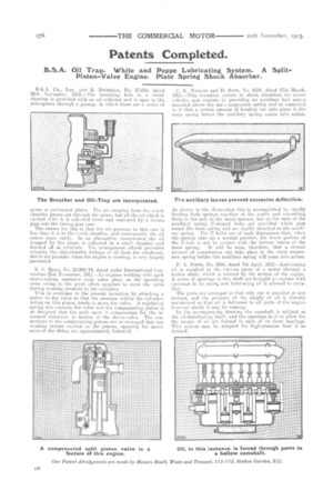
C. K. WRIGHT and B. BAIN, No, 6584, dated 17th March, 1913.—This invention relates to shock absorbers for motor vehicles and consists in providing art auxiliary leaf spring mounted above the maisi suspension spring and so connected to it that a certain amount of bending can take place in the main spring before the auxiliary spring comes into action.
As shown in the illustration this is accomplished by rigidly binding both springs together at the centre arid connecting them to the axle in the usual manner, but at the ends of the auxiliary spring IT-shaped bolts are provided which pass round the main spring and are rigidly attached to the anxiii, ary spring. The IT-bolts are of such dimensions that, when the springs take up a normal position, the lower portion of the IT-bolt is not in contact with the bottom leaves of the
main spring. It will be seen, therefore, that a certain amount of compression can take place in the main suspenskin spring before this auxiliary spring will come into action.
P. A. POPPE, No. 8084, dated 7th April, 1913.—Lubricating oil is supplied to the various parts of a motor through a hollow shaft, which is rotated by the motion of the engine. A series of openings in this shaft are brought to register with openings in its casing and lubricating oil is allowed to circulate.
The ports are arranged so that only one is unsealed at any instant, and the pressure of the supply of oil is thereby maintained so that oil is delivered to all parts of the engine however slowly it may be running.
In the accompanying drawing the camshaft is utilized as the oil-distributing shaft, and the openings in it to allow for t le escape of oil are formed in each of its three bearings. This system may be adapted for high-pressure feed if so desired.