


Patents Completed.
Page 22
If you've noticed an error in this article please click here to report it so we can fix it.
Expanding Brakes. Char-a-banes Hoods. Carburetter Improvements.
Copies of complete specifications of the patents published on this page can be obtained from the Sales Branch, Patent Office, Holborn, W.C., at the cost of sixpence for each specification.
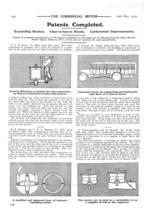
G. E. N. SUBRA, No. 9432, dated 16th April, 1914.—This C. DonsoN, No. 16,067, dated 6th July, 1914.—This inven
carburetter is provided with a main jet situated in a chokethin is designed to facilitate the handling of cape-hoods on tube in the usual manner, but there is provided, in addition, chars-a-bancs and other long vehicles. The hood is supported
a smaller auxiliary jet, which extends to a much higher level• than the main jet. The auxiliary jet is placed at one side of the choke-tube and close to the throttle, so that when the latter is very nearly closed all the air passing through it is drawn over the auxiliary jet. With the throttle in this position the suction does not affect the main jet, arid the limited fuel-supply required is drawn entirely from the smaller jet.When Ih'e throttle is fully opened, however, the suction acts on the main jet, and the major portion or the whole of the fuel-supply is given by this jet.
The throttle and choke-tube are mounted concentrically with the jet so that they can be turned round to suit various positions of the carburetter on the motor and of the actuating levers for the throttle.
R. R. IMEI.Lort AND TM. G. MORTON,' No. 3472, dated 4th March, 1915,—The accompanying drawings show an internal-expanding brake in which there are two semi-circular segments forced outwards by cams between their adjacent ends.
Instead of connecting the brake-rod directly to the spindles, a floating lever is interposed. The brake-rod operates on one end of the lever, and the other end of the lever is connected to one of the cam spindles, while it is connected at its middle point by a link to the other of the spindles. This construction gives a fully compensated action. The brake-shoes are each provided with rectangular recesses to engage blocks carried by the spider. These blocks take the braking torque so that the cams are entirely free from it.
on each side of the vehicle by a temporarily-applied radius rod, which can rest on the bottom step. A stud is provided on each side of each hood-stick, and the radius-rod is engaged with it. The rods are then swung forward and carry the hood-stick to the required position, where it is fixed in the ordinary way. This process is repeated with each of the hoed-sticks, although it may not be necessary with the front one.
Straps are provided on each hood-stick to hold it temporarily until those in advance of it have been secured in their open position. These straps can then be secured along the under side of the roof of the hood out of the way. The drawing shows the temporary radius-rod stowed on the bottom step of the vehicle.
G. CONSTANTINESCO and W. HADDON, No. 17,176, dated 20th July, 1914. This specification describes a device for supplying liquid fuel to an internal-combustion engine, acting either as a carburetter or as a supplier of liquid heavy fuel to a vaporizer.
The float-feed-chamber is arranged to deliver the liquid through a valve-controlled opening in the bottom. The valve is mounted on a flexible diaphragm at the top of the chamber. Communication is made from the upper side of this diaphragm to the engine side of the throttle valve, so that the engine suction lifts the diaphragm, and opening the valve, permits fuel to flow out.] The constant head of liquid in the floatfeed-chamber is sufficient to overcome the frictional resistance to such flow so that the engine suction can draw fuel proportionally to its own strength as the valve is opened wider.