


Patents Completed.
Page 20
If you've noticed an error in this article please click here to report it so we can fix it.
Complete specifications of the following patents will be sent to any address in the United Kingdom upon receipt of eightpence per copy at the Sales Branch, Patent Office, Holborn, W.C.
TRACK FOR ROAD LOCOMOTIVES.—Roberts and Another.—No. 16,117, dated 29th July, 1908.—This invention relates to " self-laid " tracks for road locomotives and other self-propelled vehicles. According to this invention the adjacent links are hinged together, and each alternate link has lugs that engage recesses or pockets formed in the links next to it so that a rigid track is formed when the links are in contact with the ground. The links of one set are made up of five pieces consisting of four side members and a distance piece, and the links of the other set are made up of three pieces consisting of two aide members and a distance piece. The distance pieces form a track for the wheels, and the side pieces are hinged together. These pieces may be forgings or pressedsteel stampings.
DIFFERENTIAL GE ARIN G.Marshall.—No. 1,505, dated 21st January, 1909.—This invention relates to mechanism for locking the differential gear. Keyed to the driving shaft, so as to be slidable thereon, is one member of a dog clutch ; the other member of the clutch is formed at one end of a sleeve surrounding the driving shaft, the other end of which carries the bevel pinions of the differential gear. The slidable member of the clutch is connected to a lever, and attached to this lever is a spring which always tends to draw the clutch into engagement. This lever is connected by a rod to a hand lever which moves over a quadrant. The quadrant is pivoted at cne end and is supported at the other end by a spring-pressed plunger ; a pin in the hand lever norMally engages a notch provided in the quadrant. When it is required to lock the differential gear the quadrant is pressed downward so as to release the hand lever ; the clutch will then be at
once brought into operation by the spring provided for this purpose. When it is required to release the differential gear again the hand lever is pulled back until its pin engages the notch in the quadrant.
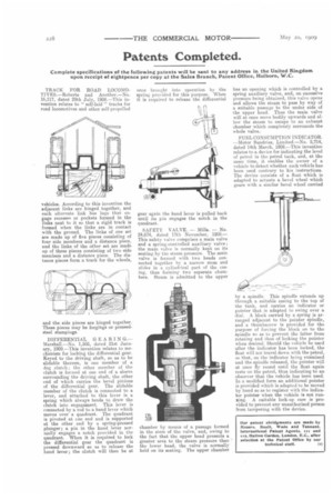
SAFETY VALVE. — Mills. — No. 24,674, dated 17th November, 1908.— This safety valve comprises a main valve and a spring-controlled auxiliary valve ; the main valve is normally kept on its seating by the steam pressure. The main valve is formed with two heads connected together by a narrow stem and slides in a cylindrical part of the easing, thus forming two separate chambers. Steam is admitted to the upper chamber by means of a passage formed in the stem of the valve, and, owing to the fact that the upper head presents a greater area to the steam pressure than the lower head, the valve is normally held on its seating. The upper chamber
has an opening which is controlled by a spring auxiliary valve, and, on excessive pressure being obtained, this valve opens and allows the steam to pass by way of a suitable passage to the under side of the upper head. Thus the main valve will at once move bodily upwards and allow the steam to escape to an exhaust chamber which completely surrounds the whole valve.
FUEL CONSUMPTION INDICATOR. —Motor Sundries, Limited.—No. 5,714, dated 14th March, 1908.—This invention relates to a device for indicating the level of petrol in the petrol tank, and, at the same time, it enables the owner of a vehicle to detect whether such vehicle has been used contrary to his instructions. The device consists of a float which is adapted to actuate a bevel wheel which gears with a similar bevel wheel carried
by a spindle. This spindle extends up through a suitable casing to the top of the tank, and carries an indicator or pointer that is adapted to swing over a dial. A block carried by a spring is arranged adjacent to the pointer spindle, and a thumbscrew is provided for the purpose of forcing the block on to the spindle so as to prevent the latter from rotating and thus of locking the pointer when desired. Should the vehicle be used after the indicator has been locked, the float will not travel down with the petrol, so that, on the indicator being examined and the spindle released, the pointer will at once fly round until the float again rests on the petrol, thus indicating to an observer that the vehicle has been used. In a modified form an additional pointer is provided which is adapted to be moved by hand so as to register with the indicator pointer when the vehicle is not running. A suitable lock-up case is provided to prevent any unauthorised person from tampering with the device.