


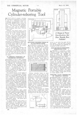
Magnetic Portable Cylinder-reboring Tool
Page 36
If you've noticed an error in this article please click here to report it so we can fix it.
D OR TABLE cylinder reboring
machines for operating on an engine in situ are a well-known means for facilitating reconditioningwork, and patent No. 542,787 shows a device of this 'nature with an added improve ment. The patentees are Brookside Engineers, Ltd., and R. Middleton, both of. Bridge Road East, Welwyn Garden City.
Hitherto, the patent states, it has been usual to clamp the boring head on to the top of the cylinder block by mean§ of bolts through adjacent cylinders, and it has been found that the proper adjustment of these bolts is a matter of difficulty, having regard to squareness and alignment. .
To avoid this, and to accelerate the operation, it is proposed to equip the boring head with a magnetic base. This will firmly attach itself to the block after energixation from the current supply to the driving motor.
. ln an accompanying drawing the magnetic base ith marked I. and the boring bar 2. An additional advantage of the scheme is that the fine iron dust from the tool will tend to adhere to the head instead of spreading about in the engine.
TO IMPROVE CONSTANCY OF .VOLUMETRIC .EFFICIENCY
CLAIMEDto give a more constant torque-speed curve to a fotir-stroke oil engine, a scheme is shown in patent No. 542,429 by Aktiebolaget Milo, Stockholm, Sweden, of which the precise actiOn is rather difficult to comprehend. The.proposal, in brief, is to employ a pressure-charger, but to • release a portion of the charge on the compression stroke by aslight reopenlog of the inlet valve.
The general layout of the engine is shown in an accompanying drawing. There is a supercharger (3), the output from which passes a thrOttle-valve (2) and a cooler •(1) before reaching' the inlet manifold. An injection pump (4) supplies the fuel, and the injectors are located in the four inlet pipes, although direct cylinder injection is mentioned as an alternative. The injection-pump control is coupled to the throttle valve (2), the latter being arranged to return the 'compressed air to the suction side during idling speeds.
Inlet ,valve operation, upon which the patent is based, is so arranged that the valve opens at 25 degrees before top dead centre, closes just before the bottom of the stroke, and then, by means of a; second smaller lobe on the cam, re-opens tor an instant on the compression stroke. The patent gives the valve diagrams, It appears that the main claim is a combination of the respective advantages commonly associated with early and late closing of the inlet valve, namely, good volumetric efficiency, in the one case, at low speeds and, in the other, at high speeds.
ACCORDING to patent No. 542,758, it has been .experimentally determined that chromium as a wearing surface for piston rings materially increases their durability. The difficulty with plating, however, is that any sharp edge on the ring may form the start of a tear-away,. and the patent shows a method of plating by which all edges are left with rounded corners. The .patentee is H. Van de Horst, of Hilversum, Holland, whose .name is already well known in connectien with the processing of cylinder liners.
Plating naturally tends to form rounded edges, and the object of the scheme is to leave the ring so that no subsequent machining will restore any sharp edges. In the case of individual rings, they are first completely machined, except that the helical split is cut only half-way through. They are next assembled in a pile, forming a cylinder, which is then plated. The helical split is completed afterwards, care being taken not to cut the plated edges of the initial groove.
When rings are formed by cutting them off from a piston-ring "pot," annular grooves are first cut where the parting-off tool will enter and a helical groove is cut where the gaps will be (see figure). Then the pot is plated and the parting-off and splitting are completed as final operations.
NEW METHOD OF PREPARING HIGH-OCTANE FUEL ,„
AMETHOD of preparing a motor. spirit of high octane value from carbon-monoxide and hydrogen is shown in patent No. 542,836, by Compagnie de Produits Chimiques et Electrometallurgiques Alais, Pads.
The complete, process is described highly technically in chemical terms, but it may be said in short that it consists of causing a mixture of carbon-monoxide and hydrogen under high pressure to traverse catalytic agents, which results in the formation of two liquids of different density. The lighter liquid is fractionally distilled into two further liquids, and these, after differing treatments: are reunited to form a highly volatile spirit having an octane number of 86.
REDUCING VALVE CONTROLLED
BY THROTTLE OPENING
rARBURETTING, arrangements for
vehicles running on gas stored in high-pressure cylinders form the subject of patent No. 542,627, from Fawcett Preston and Co., Ltd„ and J. Bather., both of Dock Road, Bromborough, Cheshire. In this scheme' the quantity' of gas is controlled in accordance with the throttle opening by varying its pressure The high-pressure cylinder (1) is equipped with the usual pressure reducing valve (2) which passes the gas, via a pipe, to a petrol carburetter (3) where it mixes with the apprbpriate quantity of air.
The essence of the invention is that the reducing valve (2) has a pressurevarying adjustment which is coupled by rodwork to the accelerator pedal (4). Gas pressure is thus increased with an -increase of throttle opening and vice versa. Although a carburetter is shown, it forms no part of the invention, being provided merely as a standby: a gas mixer may be substituted.