


THE REGENERATION OF LUBRICATING OIL:
Page 70
If you've noticed an error in this article please click here to report it so we can fix it.
A Resume of Recently Published Patent Specifications.
IT is well known that much lubricating oil is wasted through the practice of periodically changing the contents of an engine sump. The present invention claims to enable the oil to be regenerated and by so doing to separate it from all undesired contamination.
Leon Mirless and Alexander Ivanovitch Kousnetsoff, both Russians living in France, in their speeificart-c..L2 tion No. 269,148, eiTeribe an apparatus which they claim will keep the lubricating oil in an engine fit for use and free from .carbon and the lighter hydrocarbons. According to the inventors, the lubricating oil not only becomes contaminated with such petrol as may pass the piston rings, -but that cracking actually takes place, which liberates carbon, etc.
It is well known that carbon will obstruct the passages through which the oil should pass and that the lighter hydrocarbons will dilute the oil and thus reduce its. viscosity. Water vapour will' often form in the crankcase, owing to the
To Prevent Wheel Wobble.
WHEEL wobble appears to be occu
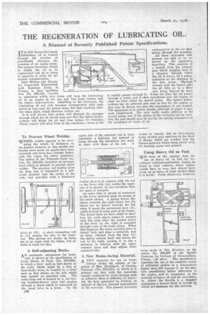
pying the minds of designers at the present moment, as this trouble has become more acute as speeds have been increased and tyres have become larger, -with the vogue for lower pressures. The patent of the Triumph Cycle Co., Ltd., No. 285,255, describes an arrangement which is claimed to prevent wheel wobble. The steering rod leading from the drop arm is connected to a bellcrank situated near the centre of the axle, and provided with a frictional
pivot at (B). A short connecting rod at (A) couples the arm to the crossrod. The springs are shown as being set at an angle with the frame, but no claim is made for this.
A Self-adjusting Brake.
AN automatic adjustment for brake rods is shown in the specification of Louis Marty, of Paris (No. 275,598), in which a lever such as that shown on the right, which might be a foot or hand-brake lever, is coupled to a lever such as that shown on the left, which may operate an expander cam. The conwicting rod is formed by a rod having buttress-shaped rings and passing through a sleeve which is connected by the usual joint to a lever. On the upper side of the serrated rod is what resembles a half-nut, but instead of being threads the serrations are made to mate with those of the rod. A s'inilar piece is in contact with the rod ( a the lower side, but, unlike the upper one, it is shorter by one serration than the space it occupies.
An outer tube or sheath is connected to the lower serrated piece by means of the screw shown. A spring forces this sleeve towards the right hand, but the sleeve cali be forced towards the left when it meets the permanent stop (A), which is fixed to some part of the frame. The dotted lines we have added to show how the outer sleeve comes in contact with this stop when the normal travel of the lever on the right is exceeded through wear of the brake shoes. When this happens, the lower serrated piece is forced back and slips a serration, and on being released from the stop (A) the spring asserts itself and forces the rod to the right, causing it to slip a serration in relation with the upper serrated piece and thus adjust itself automatically.
A New Brake-facing Material. A NEW material for use as brake
facings forms the subject of the patent of Max Kirchbach, of Coswig, Germany (No. 272,478), in which it is pointed out that with the materials usually employed for brake facings, such as asbestos, there is difficulty in removing the heat generated by friction, on account of the low thermal conductivity of the material. The present invention condensation in the air that enters through the breather.
All these unwanted substances are said to be removed by the apparatus described. This consists of a branch from the exhaust pipe which supplies heat ta a chamber threough which the oil is driven by a pump; indicated on the drawing aS the first -pump. -Through contact with the heated pipe the oil falls on to a Met and, being thinned by heat, it readily passes _through it. Prom-the filter the oil passes through a cooler and is then introduced into the engine by what we have called the second pump. The lighter hydrocarbons can be collected and used as fuel for the engine, or they may be driven out into the atmosphere, if not wanted. The apparatus is in reality simple, although on paper it may seem complicated. The only really costly addition is the second pump, but, if the claims of the inventors can be justified, the cast should soon be Met by the saving consequent on the avoidance of waste of oil.
20044. FsIZST PutAD
claims to remedy this by introducing finely divided grey cast-iron in the form of filings, which are werked into the fibrous material whilst being mixed with the bonding agent and pressed.
Using Heavy Oil as Fuel.
• NATE were of the opinion that the use of heavy oil as fuel for th ordinary internal-combustion engine as fitted to road vehicles, where engine ,speeds have to -vary, had almost been given up as being of more trouble than it is worth. Fresh efforts are, however,
being made in this direction, as the patent No. 262,407 of the Societe, Anonyme Le Carbons of Genuevilliars,
France, v.ill show. The specification describes the use of the catalytic action of activated carbon at a temperature higher than 250 degrees C. on the mixture immediately before admission to the engine, and in proportion to the quantity of heavy oil and air used therein. Above the throttle is a chamber containing a heated block of Carbon. in which are Pasaages for the mixture. '