


Spare Wheel Winch
Page 66
If you've noticed an error in this article please click here to report it so we can fix it.
THE increasing size of vehicle tyres is approaching the point at which manhandling of the spare wheel is reaching human limitations, and assistance in this connection is the object of a .scheme disclosed in patent No. 793,195. (Ford Motor Co., Ltd., 88 Regent Street, London, W.I.)
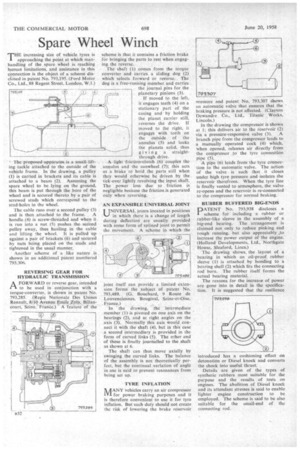
The proposed apparatusis a small lifting tackle attached to the outside of the vehicle frame. In the drawing, a pulley (1) is carried in brackets and its cable is attached to a beam (2). Assuming the spare wheel to be lying on the ground, this beam is put through the bore of the wheel and is secured thereto by a pair of screwed studs which correspond to the stud-holes in the wheel.
The cable runs over a second pulley (3) and is then attached to the frame. A handle (4) is screw-threaded and when it is run into a nut (5) pushes the second pulley away, thus hauling in the cable and lifting the wheel. it is pulled up against a pair of brackets (6) and secured by nuts being placed on the studs and tightened in the usual manner.
Another scheme of a like nature is . shown in an additional patent numbered 793,306.
REVERSING GEAR FOR HYDRAULIC TRANSMISSION
AFORWARD or reverse gear, intended to be used in conjunction with a torque-converter, is shown in patent No. 793,285. (Regie Nationale Des Usines Renault, 8/10. Avenue Emile .41a, Billancourt, Seine, France.) A feature of the
scheme is that it contains a friction brake for bringing the parts to rest when engaging the reverse.
The shaft (I) comes from the torque converter and carries a sliding dog (2) which selects forward or reverse. The dog is a free-running member and carries the journal pins for the planetary pinions (3).
If moved to the left, it engages teeth (4) on a stationary part of the casing and by holding the planet carrier still, reverses the drive. If moved to the right, it engages with teeth on the outside of the annulus (5) and locks the planets solid, thus giving a straightthrough drive.
A light friction-clutch (6) couples the annulus and the sunwheel (7); this acts as a brake to hold the parts still when they would otherwise be driven by the tick-over lightly revolving the input shaft. The power loss due to friction is negligible because the friction is generated only when reversing.
AN EXPANSIBLE UNIVERSAL JOINT
UNIVERSAL joints located in positions %-) in which there is a change of length during deflection are usually. provided with some form of splined joint to permit the movement. A seheme in which the joint itself can provide a limited extension forms the subject of patent No. 793,489. (G. Bouchard, 9 Route de Louvenciennes. Bougival, Seine-et-Oise, .France.I • In the drawing, the intermediate member (1) is pivoted on one axis on the bearings (2), and at right angles on the axis (3). Normally this axis would connect it with the shaft (4). but in this case a second intermediary is provided in the form of curved links (5). The other end of these is finally journalled to the shaft as shown at 6.
The shaft can thus move axially by swinging the curved links. The balance of the assembly is not theoretically perfect, but the continual variation of angle in use is said to prevent resonances from being set up.
TYRE INFLATION
UT ANY vehicles carry an air compressor LVI for power braking purposes and it is therefore convenient to use it for tyre inflation. But such duty should not create the risk of lowering the brake reservoir
lressure and patent No. 793,307 shows an automatic valve that ensures that the braking pressure is not affected. (Clayton Dewandre Co., Ltd., Titanic Works, Lincoln.) In the drawing the compressor is shown at 1; this delivers air to the reservoir (2)
via a pressure-responsive valve (3). A branch pipe from the compressor leads to a manually operated cock (4) which, When opened, releases air directly from the compressor to the tyre connection pipe (5).
A pipe (6) leads froin The tyre connection to the automatic valve. The action of the valve is such that it closes under high tyre pressure and isolates the reservoir therefrom. When the tyre line is finally vented to atmosphere, the valve re-opens and the reservoir is re-connected to the compressor for normal braking.
RUBBER BUFFERED BIG-ENDS
PATENT No. 793,938 discloses a scheme for including a rubber or rubber-like sleeve in the assembly of a big-end bearing. The arrangement is claimed not only to reduce pinking and rough running, but also appreciably to increase the power output of the engine. (Holland Developments, Ltd., Northgate House, Sleaford, Lincs.)
The drawing shows, the layout of a bearing in which an oil-proof rubber sleeve (1) is attached by bonding to a bearing shell (2) which fits the connecting rod bore. The rubber itself forms the actual bearing material.
The reasons for the increase of power are gone into in detail in the specification. It is suggested that the resilience introduced has a cushioning effect on detonation or Diesel knock and converts the shock into useful thrust.
Details are given of the types of synthetic rubbers most suitable for the purpose and the results of tests on engines. The abolition of Diesel knock and its attendant stresses is said to enable lighter engine construction to be employed. The scheme is said to be also suitable for the small-end of the connecting rod.