


Constant-level Pneumatic Spring
Page 58
If you've noticed an error in this article please click here to report it so we can fix it.
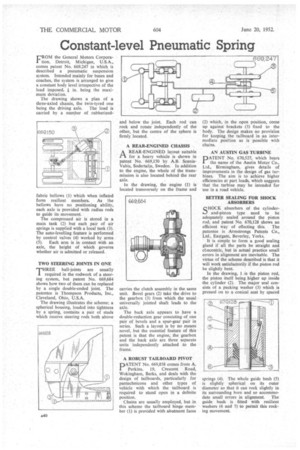
FROM the General Motors Corporation, Detroit, Michigan, U.S.A., comes patent No. 669,247 in which is described a pneumatic suspension system. Intended mainly for buses and coaches, the system is arranged to give a constant body level irrespective of the load imposed, in. being the maximum deviation.
The drawing shows a plan of a three-axlecl chassis, the twin-tyred one being the driving axle. The load is carried by a number of rubberized fabric bellows (1) which when inflated form resilient members. As the bellows have no positioning ability, each axle is provided with radius rods to guide its movement The compressed air is stored in a main tank (2) but each pair of air springs is supplied with a local tank (3). The auto-levelling feature is performed by control valves (4) worked by arms (5). Each arm is in contact with an axle, the height of which governs whether air is admitted or released.
TWO STEERING JOINTS IN ONE THREE ball-joints are usually I required in the rodwork of a steering system, but patent No. 669,684 shows how two of them can be replaced by a single double-ended joint. The patentee is Thompson Products, Inc., Cleveland, Ohio, U.S.A.
The drawing illustrates the scheme; a spherical housing, loaded into tightness by a spring, contains a pair of studs which receive steering rods both above and below the joint. Each rod can rock and rotate independently of the other, but the centre of the sphere is firmly located.
A REAR-ENGINED CHASSIS
AREAR-ENGINED layout suitable for a heavy vehicle is shown in patent No. 669,150 by A.B. ScaniaVabis, Sodertalje, Sweden. In addition to the engine, the whole of the transmission is also located behind the rear axle.
In the drawing, the engine (1) is located transversely on the frame and carries the clutch assembly in the same unit. Bevel gears (2) take the drive to the gearbox (3) from which the usual universally jointed shaft leads to the axle.
The back axle appears to have a double-reduction gear consisting of one pair of bevels and a spur-gear pair in series. Such a layout is by no means novel, but the essential feature of this patent is that the engine, the gearbox and the back axle are three separate units independently attached to the frame.
A ROBUST TAILBOARD PIVOT DATENT No. 669,858 comes from A. Perkins, 19, Crescent Road, Wokingham, Berks, and deals with the design of tailboards, particularly for pantechnicons and other types of vehicle with which the tailboard is required to stand open in a definite position.
Chains are usually employed, but in this scheme the tailboard hinge member (1) is provided with abutment faces (2) which, in the open position, come up against brackets (3) fixed to the body. The design makes no provision for keeping the tailboard in an intermediate position as is possible with chains.
AN AUSTIN GAS TURBINE
PATENT No. 670,527, which hears the name of the Austin Motor Co., Ltd., Birmingham, gives details of improvements in the design of gas turbines. The aim is to achieve higher efficiencies at part loads, which suggests that the turbine may be intended for use in a road vehicle,
'BETTER SEALING FOR SHOCK ABSORBERS
SH"I(absorbers of the cylinderand-piston type need to be adequately sealed around the piston rod, and patent No. 670,128 shows an
efficient way of effecting this. The patentee is Armstrongs Patents Co., Ltd., Eastgate, Beverley, Yorks..
It is simple to form a good sealing gland if all the parts be straight and ct.ncentric, but in actual practice small errors in alignment are inevitable. The virtue of the scheme describedis that it will work satisfactorily if the piston rod be slightly bent.
In the drawing, 1 is the piston rod, the piston itself being higher up inside the cylinder (2). The major seal consists of a packing washer (3) which is pressed on to a conical seat by spaced springs (4). The whole guide bush (5) is slightly spherical on its outer diameter so that it can rock slightly in its surrounding bore and so accommo date small errors in alignment. The guide bush is fitted with resilient washers (6 and 7) to permit this rocking movement.