


Automatic Coupling for Trailer Brakes
Page 54
If you've noticed an error in this article please click here to report it so we can fix it.
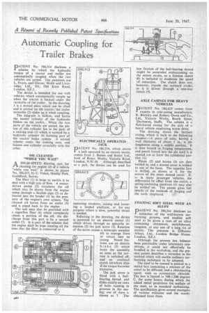
PATENT No. 586,514 discloses a scheme by .which the hydraulic brakes of a tractor and trailer are automatically coupled when the two vehicles are united. The patentees are L. Evans, and Glover, Webb and Liversidge,' Ltd., • 561, Old Kent Road, London, S.E.1.
The ,device is intended for use with vehicles which automatically couple up when the tractor is backed under the turntable of the trailer, in the drawing, 1 is a slotted plate which' can he tilted and is carried on' the tractor'the trailer turntable (2) slides up it whets couPIing.
The king-pin is hollow, and forms the master cylinder . of , the hydraulic brakes on the ,trailer. When the two Parts of the vehicle are united, the piston of this cylinder lies in the path of a rocking cam (3) which is worked by a hydraulic cylinder (4) forming part of the tractor brake system. A second scheme omits the rocking cam, and locates one cylinder co-axially with the other.
OIL CLEANED "WHILE YOU WAIT"
A HIGH-SPEED filtering unit for 1-3, cleaning the engine oil of a vehicle "while you wait" is shown ..in .patent No, 586,413, by C. Vokes, Henley Park, Guildford, Surrey.
The filter (1) is large to enable it to deal with a high rate of flow. A motordriven pump (2) circulates the oil which may be drawn from the engine sump through a flexible pipe (3) or, delivered into the header (4) by the pressure of the engine's own system. The cleaned oil leaves from an outlet (5) and is piped back to the engine.
The Unit may also be provided with a superfine filter (6) which completely cleans a portion of the oil; the discharge from this part is by a second outlet (7). It is part of the scheme that the engine shall be kept running all the time that the filter, is connected to it.
pATENT No. 586,256, which shows a jack operated by an electric motor, comes from J. Baines and Rotax Ltd., both of Rotax Works, Victoria Road, London, N.W.10. Although described as a jack, the device can be used for operating windows, raising and lowering a loaded platform, or for any purpose where a slow, powerful thrust is needed.
Referring to the drawing, the device is. powered by an electric motor (1) which drives through an epicyclic reduction (2) the jack screw (3). Rotation of the screw causes a telescopic member (4) to emerge from or return into its casing. Novel features are an electric brake (5) which locks the assembly as soon as the current is switched off, and an overload clutch (6)which slips if the torque becomes excessive.
The jack screw is fitted with a ballbearing thread and slides axially on rows of balls running in grooves in the casing; one of these is shown at 7. The low friction of the ball-bearing thread might be somewhat embarrassing on the return stroke, so a friction clutch (8) is included to moderate the speed of retraction. The clutch does not, however, impede the outward stroke, as it is driven through a one-way clutch (9).
• AXLE CASINGS FOR HEAVY VEHICLES
PATENT No. .586,623 comes from experts in axle-casing manufacture, R. Buckley and Rubery Owen and Co., Ltd., Victoria Works, Booth Street, Darlaston, Staffs. The subject is a tfabricated casing for the axle of a heavy vehicle employing worm drive.
The drawing shows the finished casing, which is built in the following manner: —A piece of tube, having a wall thickness of about 1 in., is slit lengthwise along a middle portion, it is then heated to forging temperature, and punch forced into the slit until it is opened out to form the cylindrical portion (1).
Plates (2) and bosses (3) are then welded in, and a domed cover is welded to one of the faces. The opposite face is drilled, as shown at 4, for the screws of the other domed cover. If, a,s in many passenger vehicles, the differential be offset from the centre, a spring-anchoring platform (5) may also be welded on. The patent gives full details of the methods of forging and the tools employed.
COATING SOFT STEEL WITH AN ALLOY
PATENT No. 586,241 discloses an extension of the well-known carburizing. process, and enables soft steel to be given a case of an alloy containing chromium, molybdenum, tungsten, or any one of a long list of metals. The patentee is Diffusion Alloys, Ltd., London Bridge House. • London, S.E.1.
Although the process has hitherto been practicable under laboratory conditions, it could not effectively be handled in the workshop, and the present patent describes a variation in the method which will enable ordinary carburizing technique to be adopted.
The steel to be treated is packed in a sealed box containing a mixture of the metal to be diffused, and a chlorinating agent, such as ammonium chloride. The box is heated to 700-1,200 degrees C, for some hours, during which the added metal penetrates the surface of the steel, as in standard carburizing. The specification gives several examples of various mixtures and the results obtained from them.