


MISCELLANEOUS GARAGE TIPS.
Page 31
If you've noticed an error in this article please click here to report it so we can fix it.
Some Useful Advice Contributed by Our Driver-Mechanic Readers.
"IN a recent article in The Commercial 1 Motor, writes " of Penge, I saw some references to ball-race extractors. Now, these tools are very useful in their way, and, when required, which, however—and fortiinately, perhaps—is not often, so seldom, indeed, is it that the ordinary garage finds use for such equipment, that it, rarely pays to buy it, Consequently, one which may easily be put together by the mechanic in his scare time, and from simple, easily el:dal:1:1.We raw materials, is the more welcome. " S.A.R.'s " letter runs I have just such a tool myself, and no doubt the accompanying sketch and the following description will be of interest to a good many readers of this page. I give no actual dimensions, as most readers will prefer to adopt the principles underlying this tool to their own requirements, which, naturally, differ according to circumstances.
"The materials required are t A couple of coach bolts and two pieces of mildsteel plate to form the stretcher plate and bridge plate respectively. " The heads of the coach bolts must he cut and filed away as shown, on one side, so that a• small lip only is left, with fillet where the heed joins the shank of the bolt, so that on that side the bolt will fit snugly against the inside of the ball race.
"The stretcher plate must he curved at the ends, so that it fits nicely into the inner ring of the race. Square slots to accommodate the squares shanks of the bolts must be cut in each end as shown.
The bridge plate, as its name implies, is intended to bridge the housing for the race. It must be drilled to accommodate the two coach bolts.
"When about to use this extractor, commence by setting the two bolts in position opposite each other inside the race with the specially shaped lip on each just fitting under the inner ring of the race. Gently slip the stretcher plate down between them, so as to force them apart, and hold them upright in the race. Fut a couple of i-in. nuts or other suitable packing on the edge of the housing and slip the bridge plate over the bolts, letting it rest on the packing. Put nuts en the bolts and screw them down on to the bridge plate.. Continue to apply the spanner and the ball race will gradually be withdrawn."
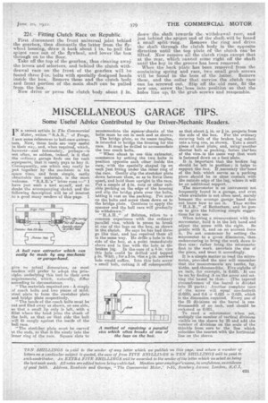
"RAIL" of Brixton,. refers to a common experience with the ordinary parallel vice, which is prone to break at one of the lugs on the box, as shown in the sketch. He says he has had three go like that, and has repaired them all in the same way, He drills a hole in the side of the box, at a point immediately above and in line with the hole in the• broken big.. In the case or a 4-in. vice this hole could be drilled and tapped i• in. Whit. ; for as-in. vice a *-in. screwed hole would suffice. Into this hole screw a small bolt, cutting it off subsequentla so that about -9a in. or a in. projects from the side of the box. For the ordinary securing bolt of the broken lug substitute a long one, as Shown. Take a small piece of steel plate, and, usingtanother shorter bolt as packing, fasten thelbox of the vice, in the same way that work is fastened dowh on a face plate.
It is important that the broken lug should be left in position ; it helps to. support .t I
he box. If necessary the,head of the bolt which serves as a packing piece should be hr close contact with the outside edge of the lug, where it will be an additional support.
The micrometer is an instrument not
frequently found in a garage, and even when available is not often used, mainly became the average garage hand does not know how to use it. Thus writes
H.A.l3,," of Rotherham, and he goes on to give the following simple suggestions for its use.
When taking. a measurement with the micrometer, hold it in the left hand and adjust the screw with the right. Be gentle with it, and on no account force it. Do not commence by setting the micrometer to a given dimension, then endeavouring to bring the work down to that size: rather bring the micrometer first to the work, ascertain the size of the piece, and treat it accordingly.
It is a simple matter to read the micro
meter, provided the user will remember that the measurements are tenths, fora tieths, and-thousandths. Five eighths of an inch, for example, is 0.625. It can be set by finding .6 on the screw and set ting the barrel to that. (The tapered circumference of the barrel is divided info 25 parts.) Another complete fairy of the screw will equal one-fortieth (0.025), and 0.6 + 0.025 = 0.625, which is the dimension required. Every one of the 25 divisions on the barrel is onethousandth of an inch, -and. should. be reckoned as 0.001.
To read a micrometer when set, multiply the number of vertical divisions visible on the sleeve by 25 and add the number of divisions on the scale of the thimble from zero to the line which coincides the nearest with the horizontal line on the sleeve.