


HINTS ON MAINTENANCE.
Page 30
Page 31
If you've noticed an error in this article please click here to report it so we can fix it.
How to Get the Best Out of a Vehicle, to Secure Reliability and to Avoid Trouble.
CONTRIBUTIONS are invited for this pagefrom fleet managers, drivers, garage foremen, and mechanics, works staff and draughtsmen, and will he paid for on a generous scale. Every system, make, and type of commercial motor vehicle will be dealt with, and the matter should be written with a view to the disclosure of workshop and garage practice in the maintenance of a vehicle—practices which, whilst they may be quite normal, are peculiar to the particular vehicle and may not be generally known to those responsible for its running. Expedients and suggestions for overcoming roadside and other troubles are covered in the following page, dealing with letters from our driver, and mechanic readers. Communications should be addressed to " The Editor, The Commercial Motor, 7-15, Rosebery Avenue, London, E.C.1."
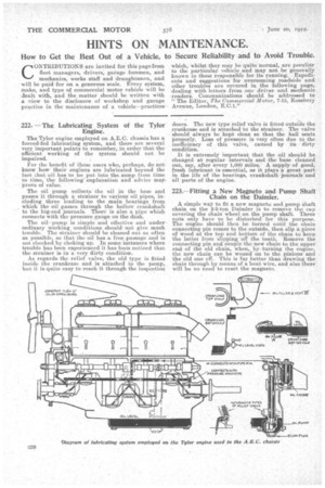
222. -The Lubricating System of the Tylor Engine.
The Tylor engine employed on A.E.C. chassis has a forced-fed lubricating system, and there are several very important points to remember, in order that the efficient working of the system should not be impaired.
For the benefit of those users who, perhaps, do not know how their engines are lubricated beyond the fact that oil has to be put into the. sump from time to time, the following explanatioii and advice may prove of value.
The oil pump collects the oil in the base and passes it through a strainer to various oil pipes, including three leading to the main bearings from which the oil passes through the hollow crankshaft to the big-end Journals. There is also a pipe which connects with the pressure gauge on the dash.
The oil-pump is simple and effective and under ordinary working conditions should • not give much trouble. The strainer should be cleaned out as often as possible, so that the oil has a. free passage and is not checked by choking up. In some instances where trouble has been experienced it has-been noticed that the strainer is in a very dirty condition.
As regards the relief valve, the old type is fitted inside the crankcase and is attached to the pump, but it is quite easy to reach it through the inspection
doors. The new type relief valve is fitted outside the crankcase and is attached to the strainer. The valve should always be kept clean so that the ball seats properly. Loss of pressure is very often due to the inefficiency of this valve, caused by its dirty condition.
It is extremely important that the oil should be changed at regular intervals and the base cleaned out, say, after. every 1,000 miles. A supply of good, fresh luleTicant is essential, as it plays a great part in the life of the bearings, crankshaft journals and all parts of the engine.
223.—Fitting a New Magneto and Pump Shaft Chain on the Daimler.
A simple way to fit a new magneto and pump 'shaft chain on the 2-3-tan Daimler is to remove the cap covering the chain wheel on the pump shaft. Three nuts only have to he disturbed for this purpose. The engine should then be turned until the chain connecting pin comes to the outside, then slip a piece of wood at the ton and bottom of the chain to keep the latter from slipping off the teeth. Remove the connecting pin and couple the new chain to the upper end of the old chain, when, by turning the engine, the new chain can be wound on to the pinions and the old one off. This is far better than drawing the chain through by means of a bent wire, and also there will be no need to reset the magneto.
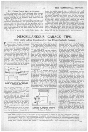
224. --Fitting Clutch Race on Republic.
First disconnect the front universal joint • behind the gearbox, then dismantle the latter from the flywheel housing, draw it back about 1 in. to pull the spigot race out of the flywheel, and lower the box
through on to the floor. . • Take off the top of the gearbox, thus clearing away the levers and selectors, and behind the clutch withdrawal race on the front of the gearbox will be found three 1-in. bolts with specially designed heads inside the box. Remove these and the clutch body and front portion of the main shaft can be pulled from the box..
Now drive or press the clutch body about. in. down the shaft towards the withdrawal race, and just behind the spigot end of the shaft.will be found
a small split ,ring. Remove the ring and drive the shaft through the clutch body in the opposite direction until the top plate of the clutch can be lifted. • Now remove all the clutch rings except that at the rear, which cannot come right off the shaft until the key in the groove has been removed-. . When the back plate has been removed from the containing spring and race, two small grub screws will he found in the boss of the latter. Remove these, and the collar that carries the clutch race can be screwed out. Slip Off the old race, fit the new one, screw the into position so that the holes line up, fit the grub screws and reassemble.