


The Latest Hele-Shaw Hydraulic System.
Page 14
Page 15
Page 16
If you've noticed an error in this article please click here to report it so we can fix it.
85 per cent. Efficiency Claimed on Full Stroke.
New transmission systems, er supposed improvements upon old ones, crop up with remarkable regularity, and with almost equal regularity are laid aside amongst the forgotten things of yesterday. From time to time motor engineers have had before them numerous systems which were so obviously foolish that one was impelled to wonder why nature should play such scurvy tricks with their inventors' brains. Some of the old hydraulic systems were amongst the least practicable of the discarded inventions, yet the principle of power transmission through the medium of a liquid is one that has undoubted claims for careful consideration by thoughtful engineers. The irresistible power of a liquid, when under pressure and suitably controlled, has long been known and appreciated, and has been employed largely on slowmoving machinery, but some of the crude and. ill-considered hydraulic power-transmission schemes, which have been introduced during past years, brought the system to a state of apparent neglect, and, as a consequence, development has been rather slow—if not strangled. Hydraulic transmission presents many difficulties, and only by years of persistent effort, and the expenditure of large sums of money, has Dr. Hele-Shaw, F.R.S.. at last developed and demonstrated a system which in many respects is unique.
The Functions of Hydraulic Gears.
In all hydraulic systems of trailsmission, the essential details include a pump which delivers the working fluid to one or more hydraulic motors, which may be direct coupled to the axle, wheel, or other Piece of mechanism which it is intended to drive. Tf oil be employed as a working fluid the whole system is self-lubricating, and there must be a. minimum amount of friction because the ever-present film of oil prevents actual metallic contact of the working parts, and under all conditions of work this oil film is maintained ; the harder the machine is worked the more assured is the continuity of the oil film because of the increased pressure of the contained oil. This property of automatic lubrication, which is a most. valuable feature of the Hele-Shaw system, makes it almost impossible for the working parts to wear out. The functions of a hydraulic system should be the provision of an infinitely-variable range of drivenshaft speeds in inverse relation to the torque of the same shaft, and for this purpose it is usual to design the pump so that, while working at prae+;eslly constant speed, the volume of oil delivered, and its pressure, may be varied throughout a range sufficient for the machine
which is to be driven. Further, if the system is to be successfully applied to motor-vehicle propulsion, the pump must be capable of being driven at high speeds, it must be positive in its action, be of reasonable weight and first cost, and should prove efficient in its working. It. is claimed by Cornpayne, Ltd., of 64, Victoria Street, S.W., which company is now working the HeleShaw patents, that the new HeleShaw system fulfils all the above requirements, and further that the working parts are in almost perfect balance, and that, although pressures as high as 2000 lb. per sq. in. may be employed, no packing materials or glands are needed or Pro vided.
Description of the New Pump.
The ilele-Shaw pump has been standardized for most purposes in the form of a rotary positiveplunger type with seven cylinders. its operation will be more easily understood after ref erence to Fig. 3, which shows a section through the cylinders and the central vatve, or " D " tube, as it, is termed by Dr. Hele-Shaw. The cylinders (C) are rotated by the prime mover, and each of the pistons is provided with a gudgeon pin (G), which passes through slots in the cylinder walls, and is provided at each end with a slipper (5) ; these slippers work in annular grooves in a" floating guide ring" (F in Figs. 4 and 7), which guide ring is mounted on ball bear. ings, independent of the cylinder body. The guide-ring bearings are carried in sliding housings (H in Fig. 4), which permit of the floating ring's being thrown eccentric to the cylinder body. The distribution of oil to the various cylinders is effected through suitably-shaped ports in the stationary central valve or "T) " tube.
Operation of the Pump.
If we assume that the cylinder body is to be rotated in the diree tion of the arrow shown in Fig. 3, and the position of the floating guide ring be such as to cause the gudgeon pin path to be eccentric to the cylinder body, the pistons will be caused to move in and out of the cylinders as the cylinder body is rotated. As each of the pistons moves outward in its cylinder, a partial vacuum will be created below it, so that the working fluid will be forced into the cylinder by
atmospheric pressure through the port P, whilst, on the other hand, each piston, as it approaches the centre of the cylinder body, will force the oil through the port Q, and thence to the hydraulic motor. If, now, the gudgeonpin circle, or path (E), be moved so that its centre coincides with that of the cylinder body, the two will then rotate about the same centre, and the pistons will have no motion relative to the cylinders. Continuing the movement of the floating guide ring further, its position may be changed gradually from full eccentricity on the left to full eccentricity on the right, the effect of this change being to reverse the flow of the liquid in the service pipes. By varying the amount of eccentricity on either side of the centre of the cylinder body, the discharge of the liquid may infinitely be varied from zero 1.o the maximum capacity of the pump.
How Mechanical Friction is Reduced to a Minimum.
It should be noted that when the cylinder body is revolved, the floating ring (F) rotates with it. because the resistance of the slippers (S) is greater than that of the ball bear
ings on which the floating ring is mounted. When the floating ring is in its central position, the slippers make no movement in their annular guide grooves, but in all positions of eccentricity of the floating ring the piston slippers move to and fro within their annular guides to an extent which is directly proportional to the piston stroke.
By the introduction of this floating guide ring, sliding friction has been reduced to a minimum, and the total efficiency of the pump greatly increased. The parts which are subject to the greatest wear are obviously the central bore of the cylinder body (0) and the external diameter of the fixed valve or " D" tube, but, as already stated, a film of oil is always maintained between these faces, and as the pressure in the system is increased, and the load on this bearing, becomes greater, the pressure of the film of oil in the bearing also rises, and this tends to counteract the effect of the increased load. It has been found after lengthy experience that practically no wear takes place on these parts.
Practical Advantages of the System.
Probably the three most practical advantages possessed by the latest
Hele-Shaw pump are the uniform and steady discharge from the pump at all pressures, the almost perfect balance of the rotating parts, and the long life of the component details. Observed tests in the laboratory have shown, by the steadiness of the pressure gauges at all pressures when the pump is working, that the discharge is remarkably uniform, notwithstanding the fact that oil is practically incompressible.
In regard to the balance of the pump, the writer has had an opportunity of observing the system at work both in the laboratory and on a three-ton Albion chassis, and was pleased to note the almost complete absence of vibration at high speeds. This balancing is attributable to the fact that although the stroke of the pumps is, effected by one member being mounted eccentric to another, yet each rotates about its own fixed centre, and although these centres may be adjusted relative to each other in order to produce any change in volume required, yet they are absolutely independent members so far as rotatory balance is concerned.
The inertia forces are also provided for, because the acceleration of those slippers and pistons above the horizontal centre line of the gear is exactly counter-balanced by the retardation of precisely similar parts below the centre line. There is, however, a third kind of balanc ing that has to be considered, and that is the pressure which is due to the fact that all the working strokes of the plungers take place on one-half of the pump only, and consequently a large force is neces sary to vary the amount of eccen tricity of the floating ring. In some sizes of pumps the ball bearings for the floating ring (F), are housed in
members (H, Fig. 4), which in turn are mounted between parallel guide
bars (HGB, Fig. 4), and in these guide bars the bearing housing, and consequently the floating ring, may be moved endwise be means of a control rod. An alternative method of moving the floating ring is shown in Fig. 7, where it may be seen that the bearing housings for the floating ring (F) are provided with lugs, and these lugs in turn are connected by shon levers to two spindles (0, 0, Fig. 7), which spindles are inter-connected externally. The advantages attending the use of the latter method are
that instead of haying the sliding friezion of the guide bars (H, G. B. Fig. 4), the only friction to be overe -!me is that on the two spindles (0, 0, Fig. 7).
Tests Have Shown High Efficiency.
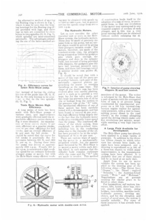
A long series of tests has been made with Hele-Shaw pumps of various sizes, and improvements were gradually effected until the re markable efficiency curves shown in Fig. 5 were obtained. An examination of these curves shows 73 per cent. efficiency at a, quarter stroke, over 80 per cent, efficiency for half stroke, and an overall efficiency of
90 per cent. for full stroke. It Fhould be noted that the curve for full stroke is practically flat for pressures between 800 lb. and 1200 lb. per sq. in. During these tests the pump was driven at approximately 1000 r.p.m. Usually 200 to 250 r.p.m. is considered a high working speed for an ordinary hydraulic plunger pump or motor, but with the Hele-Shaw nump efficient work ing may be obtained with speeds up to 1200 or 1400 r.p.m., but in general service the speeds range from 800 to 100(1 r.p.m.
The Hydraulic Motors.
Let us now consider the other essential unit. or units in the HoleShaw system, the hydraulic motors. These may be made of precisely the same form as the pump, but no useful object would be served by giving their plungers variable stroke. The motors, therefore, are made of the constant-stroke type, the plungers being actuated as before by gudgeon pins which pass through the plungers and slots in the cylinder walls, but instead of being provided with slippers, the gudgeon pins (G) have ball bearings mounted upon them, and these ball bearings travel in annular double cam guides (K, Fig. 6). It should be noted that with a motor of this type all the parts are in perfect balance, each pair of diametrically opposed pistons approaching the centre or receding therefrom at the same time. The shape of the double cam has been evolved after very careful plotting, and it is such as to provide a very large lap for the valve ports, and this large lap prevents loss of oil by slip or leakage from the suction to the pressure side of the " D " tube. The mechanical efficiency of one of these motors has been carefully tested with a dynamometer, and has been found to exceed 95 per cent., this high efficiency being largely due to the fact that the hydraulic motor works at a considerably lower speed than the pump. The combined efficiency of the whole system, from crankshaft to driving-wheel tires, including loss in the conducting tubes due to the viscosity of the oil, has been proved to be in the neighbourhood of 75 to 85 per cent.
There are various ways of applying the motor to a mechanicallypropelled vehicle, but the manner most favoured by Dr. Hele-Shaw is to mount a motor within each driving wheel, in such manner that the cylinder body remains stationary while the cams and the "D " tube are made to revolve. This method of construction lends itself to the adoption of a cam of wavy, or corrugated form, so that one revolution of the motor may correspond to any required number of strokes of each plunger, and in this way a very great turning effort can be obtained without unduly enlarging the di
men sions of the motor. The writer is informed by Dr. Hele-Shaw that a pair of motors with the corrugated form of cam is at present being constructed for experimental purposes on a 100 h.p. internal-combustion engine tractor for agricultural purposes, with a view to transmitting power direct to the road wheels ; at the normal ploughing speed the driving wheels make only five revolutions per minute, meanwhile exerting a very high tractive effort.
A Large Field Available for Development.
The Hele-Shaw pump has already been applied to a large variety of purposes. In addition to the threeton Albion chassis to which reference has already been made, designs have been prepared, and a drawing is reproduced on p. 340, of a three-ton chassis to which many improvements in the transmission system have been effected. It is probable that one of these chassis will be in hand at an early date. Apart from its use on motor vehicles the system has been applied to the steering gear of the following ships :—The Orient liner " Orama," : the Diesel engined " Selandia " : the Austrian-Lloyd vessels " Wein " and " Helouan." Negotiations are at present pending for similar gears to be fitted to other ships.
For locomotives, rail motors, traverses, lifts, hoists, sheer legs, electric search light towers, swing bridges, turn-tables, machine tools, 11141r:wile presses, riveting machines. and for the elevation and control of naval guns, the system is equally suitable. For some of these purposes it has already been applied.