


An Injection Pump for Small Engines
Page 66
If you've noticed an error in this article please click here to report it so we can fix it.
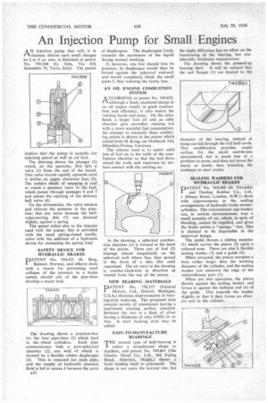
AN injection pump that will, it is claimed, deliver such small charges as 2 to 4 cu. mm. is disclosed in patent No. 749,568 (G. Sola, Via XX Settembre 74, Turin, Italy). The pa era
implies that the pump is suitable for injectini petrol' as well is oil fuel.
The drawing shows the plunger (1) which, on the upstroke, first lifts a valve (2) from the end of the barrel. This valve travels rapidly upwards until it strikes an upper abutment face (3). The sudden shadk of stopping is said to create a pressure wave in the fuel, which passes through passages 4 and 5 and assists the opening of the delivery ball valve (6).
On the downstroke, the valve retracts and relieves the pressure in the pipeline; this can occur because the ballvalve-seating disc (7) can descend slightly against a spring.
The patent refers also to the injector used with the pump; this is provided with the usual spring-closed needlevalve with the addition of a hydraulic device for increasing the spring load.
SAFETY DEVICE FOR HYDRAULIC BRAKES
PATENT No. 749,421 (K. Berg, Reistad, Norway, and others) deals with a means for preventing total collapse of the pressure in a brake system should one of the pipe-lines develop a major leak.
The drawing shows a junction-box for the four pipe-lines (1) which lead to the wheel cylinders. Each pipe communicates with a part-spherical chamber (2), one wall of which is formed by a flexible rubber diaphragm (3). This is repeated for each pipe, and the supply of hydraulic pressure fluid is led to spaces 4 between the pairs s32 of diaphragms. The diaphragins freely transmit the movement of the liquid during normal working.
If, however, one line should lose its pressure, its diaphragm would then be forced against the spherical end-wall and would completely block the small ports 5, thus isolating the faulty line.
AN OIL ENGINE COMBUSTION SYSTEM
A CCORD1NG to patent No. 749,825, 1-1, although a finely atomized charge in an oil engine results in good combustion and efficiency, it also makes the running harsh and noisy. On the other hand, a larger fuel jet and an eddy chamber give smoother running but with a more wasteful fuel consumption. An attempt to reconcile these conflicting points is shown in the patent which comes from H. Krug, am Stadtpark 33d, Munchen-Pasing, Germany.
The scheme used is to squirt solid jets of fuel on to the walls of the combustion chamber so that the fuel flows round the walls and vaporizes by surface contact with the swirling air.
In the drawing, a spherical combustion chamber (I) is formed in the head of the piston. Three jets of fuel (2) impinge almost tangentially on the spherical wall where they then spread in the form of a thin film until vaporized. The air swirl in the drawing is counter-clockwise in direction as viewed from the top of the piston.
NEW BEARING MATERIALS
PATENT No. 750,557 (General Motors, Ltd., Detroit, Michigan, U.S.A.) discloses improvements in bearing-strip make-up. The proposed strip consists mostly of aluminium having a lead-based wearing surface attached. Between the two is a flash of silver having a thickness of only 0.0001 in. or less. A steel backing strip may be added.
EASY-TO-MANUFACTURE BEARINGS
THE normal type of half-bearing is rather a complicated shape to machine, and patent No. 749,861 (The • Glacier Metal Co., Ltd, 368 Ealing Road, Alperton, Middx.) shows a• form lending itself to presswork. The shape is not quite the normal one, but
the slight difference has no effect on the functioning of the bearing, but considerably facilitates manufacture.
The drawing shows the pressed-up bearing shell. It will be noticed that the end flanges (1) are lted to the diameter of the bearing, instead of being carried through the full half-circle. This modification provides ample surface for the small end-thrusts encountered, but is much less of a problem to press, and does not stress the metal so much, thus lessening the tendency to start cracks.
SIEALING WASHERS FOR HYDRAULIC BRAKES
PATENT No. 749,488 (H. Trevaskis and Dunlop Rubber Co., Ltd., I Albany Street, London, N.W.1) deals with improvements in the scaling arrangements of hydraulic brake mastercylinders. The conventional cup-Washer can, in certain circumstances, trap a small quantity of air, which, in spite of bleeding, cannot . be expelled, and gives the brake action a " spongy" feel. This is claimed to be impossible in the improved design.
The pedal thrusts a sliding member (1) which carries the piston (2) upon a reduced nose. There are also 'a flexible sealing washer (3) and a guide (4).
When retracted, the piston occupies a bore rather larger than the working diameter of the cylinder, and the sealing washer just uncovers the edge of The replenishment port (5)..
When put into operation, the piston thrusts against the scaling washer and forces it against the bulbous end (6) of the guide. This expands the washer slightly so that it then forms an effect. ive seal in the cylinder.