


Built-up Crankshafts
Page 58
If you've noticed an error in this article please click here to report it so we can fix it.
DATENT Vo. 654,121, shows a
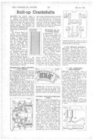
methoi of building-up crankshafts by welding, and although intended primarily for the larger sizes of marine engine, the scheme may quite conceivably be of use in connection with smaller engines. The patentees are Richardsons Westgarth anr.1 Co., Ltd.. and others, Northumberland Engine Works, Wallsend-onTyne.
The drawing shows the primary units, comprising journals and webs, the latter being in the form of dished forgings. A spigot (1) on each journal is first welded into its mating web-bore and the crankpins are similarly dealt with; this forms the first stage in assembly, and is shown in the lower drawing.
Next, theweb faces• (2) are machined square with the bearings, and a final weld is then performed round the edges of the webs and on the smaller spigots (3). The whole assembly is then stress-relieved when it is ready for the final machining operations. The space within the hollow webs may be used for housing balance-weights if desired.
6 53.708
,
DIFFERENTIAL DRIVE BETWEEN TWIN WHEELS.
TO provide differential action between
the individual wheels of a twin pair is the aim of a scheme shown in patent No. 654,138, by the Dualoc Engineering Co., Rockford 1liinoi, .U.S.A. The Object appears to be to prevent tyre scuffing during 'Cornering. ,
The differential gear proposed is of the limited-action type, a solid drive being created if the limit, be overrun. Referring to the drawing, the drive arrives via a central member (1) upon which . the two wheels are freely mounted. The central member forms the planet-carrier of an all-spur-gear differential, consisting of pinions (2) and internal gear-rings (3) on the wheels. The essence of the action is that one of
each group of planet-pinions is mounted ' on a screwed spindle (4) instead of on the usual plain bearing. In operation, if a pinion should rotate a considerable amount, it would screw along its spindle and lock up on the end-face. This immediately terminates the differential action and gives a solid drive.
RETAINING OIL ON CYLINDER BORES
CHROM1UM makes an ideal wearing surface for the bores of cylinders and liners, but it has the property of resisting oil-wetting, and bores have therefore to be treated in some way to break down this resistance. A method of doing this is shown in patent No. 653,708. by S. Hedgecock, and the Laystall Engineering Co., Ltd., 53, Great Suffolk Street, London. S.E.1. 11■10tel 404,
The proposed treatment is • to cut numerous small helical giooves on the surface, as shown in the drawing. Perhaps scratches would be a better term, because they are only 24 millionths of an inch deep, and are much closer than is shown in the drawing, which is intended only to illustrate the pattern. The scratches are cut by using a lap charged with diamond chippings. The operadon is performed after the liner has been bored to its finish dimension.
FLEXIBLE MOUNTING FOR TWIN TYRES
WHEN a twin-tyred wheel travels on VV, a cambered road, the rigidity of the wheel assembly usually causes the inside tyre .to carry a greater load than
its. outside • neighbour. Patent No. 653,895 shows a scheme for equalizing the load in these ,cjrcumstances; the patentee is the Dunlop Rubber Co., Ltd., 1, Albany Street, London; N.W.1. The rim assembly is provided with inwardly directed teeth (1), whilst the hub member has outward pointing projections (2). Rubber blocks (3) are forced into the intervening spaces, and convert the two units into an assembly which, although rigid in the driving sense, nevertheless allows the rim assembly to rock sufficiently to suit road camber. The rubber blocks are not bonded to their enclosing faces, although they may be faced with thin
bonded-on plates. (4). They are held in place by pins (5) which locate in corresponding holes in the teeth.
A NEW FRICTION MATERIAL
DATENT No. 653,273, from the Bendix Aviation Corp.; U.S.A., describes an improved friction material for clutch and brake facings. The new material contains an:asbestos base, with the addition of silica aerogel. cordolite and a binding medium of the phenolformaldehyde type. The patent gives many different formulw, all of which are said to give a material having better frictional properties and improved heat resistance.
ANEW SUSPENSION ARRANGEMENT
PA TE N T No. 654.131 shows a vehicle suspension scheme in which a leaf-spring, a shock-absorber and a dashpot are all incorporated as a unit. The patentee is W. Black, 22, St. Ninian's Road, Edinburgh, 12.
The drawing shows one end of the assembly in which a rectangular frame has its upper member (1) fixed to,_the chassis and the bottom bar (2) attached to the axle. End-pieces 3 are telescopic, and a helical spring is enclosed in the upper casing (4) to act as a shock'absorber. The main semi-elliptic leafspring (5) is slidably linked to plunger 6 of a hydraulic damping Cylinder (7). The last-named unit consists of a liquid-filled cylinder having leak-ports drilled through the piston. It is claimed that the scheme can readily be incorporated in existing vehicles without extensive modifications to thern,..