


Injection Pumps for Petrol Engines
Page 62
If you've noticed an error in this article please click here to report it so we can fix it.
A Resume of Recently Published Patent Specifications
THE well-known name of H. R. Ricardo, 21, Suffolk Street, London, S.W.1, appears in patent No. 411,117, which describes methods of controlling metering pumps used for supplying the fuel needs of a petrol engine, instead of the more usual carburetter. The advantages claimed for the scheme are several:—The cooling effect produced by the evaporation occurs usefully in the cylinder instead of in the carburetter, where it is often a nuisance; fire risk from back-fire is abolished, there being only air in the induction pipe; and full power can be developed instantly from a cold start.
When considering this scheme, however, it should be borne in mind that if the engine should be overrun by the vehicle, fuel is still injected at a rate proportional to that speed, irrespective of whether the engine is driving or not. It is true that the rate of injection is only that required for idling, but even this amount may disturb the lubrication of the engine.
The object of this invention is to overcome this disadvantage, as well as to provide an enriching device for periods when running on full throttle.
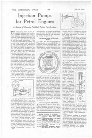
The drawing shows a diagrammatic view of the proposed modifications. Driven by the engine is an injection
pump (3), protruding from which is the control member (2). The lever (7) represents the manual control of an air-throttle (6), which controls the degree of vacuum in the air inlet and, ultimately, the quantity of fuel injected. This is brought about by the inlet suction operating on the piston (1) through pipe 5. The lever (7) at the end of its movement (as shown) comes into contact with rod 2 and, superseding the vacuum control, gives the extra enrichment for full throttle.
To guard against injection while overrunning, a small conduit (4) connects the exhaust pipe with the air inlet, so that when truly idling a small amount of burnt gas may enter the air inlet; this keeps the pressure higher than that caused by overrunning. During overrunning, however, the n48 small quantity of exhaust gas is insufficient to affect the high suction, which automatically cuts off the fuel supply by moving the piston (1).
The Self-energizing of Hydraulic Brakes.
DATENT No. 411,616 describes improvements provements in hydraulic brakes intended to increase their efficiency. The patentee is the Hydraulic Brake Co., West Hancock Avenue, Detroit, U.S.A. The• drawing shows a brake system having two hydraulic cylinders. Considering the action on one shoe (3) alone, this is moved to the left at the top by one of the hydraulic pistons. The shoe pivots about pin 2, which, it will be noted, is slightly nearer the centre than is the hydraulic cylinder. The effect of this is to make the shoe self-wrapping, which materially multiplies the pressure applied. (The direction of rotation is shown by the arrow.) The opposite shoe operates similarly, being worked by the lower cylinder and pivoting around pin 1. The cylinders are shown double-ended, the reason for this being that, by this means, the principle can be applied to reverse movement as well.
Automatic Ignition Adjustment.
A CCORDLNU to Robert Bosch, A.G., .1-1 of Stuttgart, Germany, automatic ignition advance operated by the engine suction, as hitherto used, suffers from the defect that a certain degree of
vacuum does not necessarily indicate a definite state of engine condition, even when additionally controlled by the throttle rod.
Patent No. 410,420 shows a proposed improvement in this type of control. The drawing, which is purely diagrammatic, shows the magneto timing lever (4) controlled by an arm (1), operated by an engine-driven governor (2). The far end of the arm is linked, via a bellcrank, to a cylinder and piston (3) connected to .the induction pipe. By this means the coupling leverage between the lever (4) and the arm (1) is varied by the degree of vacuum, the result of which is that the governor control is intensified at .low engine speeds, and diminished as the speed rises.
Preventing Dribble in Fuel Nozzles.
PATENT No. 411,113 describes a modification to fuel-injection pumps of the type in which the fuel is compressed against an accumulator or , counter-piston, and has for its object the prevention of continued pressure in the pipe-line a f t er injection. The patentee is E. Schaeren, Florastrasse 38, Solothurn, Switzerland.
T h e drawing shows a pump at the t op dead
centre position. -Encl has been
co m ptessed in chamber 2 and has passed to the pipeline, via ports 3, 4 and 5. The spring-loaded accumulator piston is shown at 1.
It has useally been the practice .(f o r mechanical reasons) to make
the piston (1) larger in diameter then the main piston (6). This has meant that upon the descent of the pistons the volume of space 2 has decreased, the result of which has been to inject a little extra fuel whilst ports 4 and 5 were in register, thus promoting a dribble.
The inventor proposes to overcome this feature by making the main piston (6) larger than the counter-piston (as shown in the drawing), with the result that immediately the pistons start to descend a suction instead of a Pressure is set up in chamber 2, which promptiv terminates injection by causing a sudden pressure drop in the system.