


A New Entrant to the Electrical Equipment Field
Page 59
If you've noticed an error in this article please click here to report it so we can fix it.
Many Interesting and Practical Features in New Salisbury Lighting and Starting Components for Commercial Vehicles
ACOMPLETE lighting and starting equipment, designed to meet the requirements of commercial vehicles, has recently been developed by Mr. A. J. Salisbury, la Grosvenor Gardens, London, 3.W.1. The equipment presents some interesting features, and it is noteworthy that a number of sets is now being operated experimentally on the London Passenger Transport Board's buses.
Increased internal lighting, and the heavy load imposed by other equipment on modern buses, have necessitated a heavy output from the dynamo. At the same time, however, the weight is rigidly limited. The Salisbury dynamo has, therefore, been designed with the object of gaining increased output without exceeding a predetermined limit of weight and size.
Maximum Output at Low Speeds.
In addition to the dynamo, the equipment includes a voltage-control regulator, a cut out and a starter motor having a patented drive. The last-named is adaptable to other makes of starter, and it is claimed that it augments the reliability of this component..
The 24-volt generator is of the plainshunt type, specially designed for use with the vibratory type of regulator. With a diameter of 8 ins, and an overall length of 14 ins., the weight of the machine is 110 lb.
Ventilation is a point of special interest, a fan being mounted at the commutator end, so arranged as to provide axial ventilation through the armature and commutator; it also draws air over the outer surface of the armature, between the field coils and over the surface of the commutator. This arrangement has several advantages, in that carbon dust from the brushes is drawn straight out of the machine, the cooling of the commutator is improved and the fan, being interposed between the end bearing and the commutator, ensures that no grease can seep through on to the commutator.
The armature is built up on a spider shaft, the grooves of the spider forming ventilating ducts through which the air is drawn.
The outstanding characteristic of the dynamo, which is rated at 1,250 watts, is the low speed at which it will give its full output; with a cut-in speed of 530 r.p.m. when cold and 580 r.p.m. when hot, the full output is attained at 670 r.p.m. and 700 r.p.m. respectively. The maximum speed for normal operation is 4,000 r.p.m., with a maximum safe speed of 6,000 r.p.m. The regulator is of the vibratory type, in which an armature alternately inserts and short-circuits a resistance in the field circuit of the generator. Mechanically, the construction of the regulator is very rigid, and the setting and operation are unaffected by road vibration. The cut-out is of similar mechanical construction to the vibrator units and is mounted on the same insulating panel.
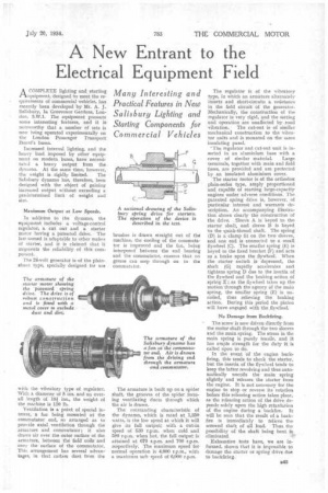
' The regulator and cut-out uuit is inserted in an aluminium base with a cover of similar material. Large terminals, together with main and field fuses, are provided and are protected by an insulated aluminium cover. The starter Motor is of the orthodox plain-series type, amply proportioned and capable of starting large-capacity engines under adverse conditions. The patented spring drive is, however, of particular interest and warrants description. An accompanying illustration shows clearly the construction of the drive. Sleeve A is keyed to the starter shaft, and sleeve B is keyed to the quick-thread shaft. The spring (D) is a clamp fit on the two sleeves, and one end is connected to a small flywheel (C). The smaller spring (E) is keyed to the fixed bracket (F) and acts as a brake upon the flywheel. When the starter switch is depressed, the shaft (G) rapidly accelerates and tightens spring D due to the inertia of the flywheel and the braking action of spring E; as the flywheel takes up the motion through the agency of the main spring, the smaller spring (E) is uncoiled, thus relieving the braking action. During this period the pinion will have engaged with the flywheel.
No Damage from Backfiring.
The screw is now driven directly from the motor shaft through the two sleeves and the main spring. The stress in the main spring is purely tensile, and it has ample strength for the duty it is called upon to do.
In the event of the engine backfiring, this tends to check the starter, but the inertia of the flywheel tends to keep the latter revolving and thus automatically uncoils the main spring slightly and releases the starter from the engine. It is not necessary for the engine to stop or reverse its rotation before this releasing action takes place. as the releasing action of the drive depends solely upon the high retardation of the engine during a backfire. It will be seen that the result of a backfire is immediately to relieve the screwed shaft of all load. Thus the possibility of the shaft being bent is eliminated
Exhaustive tests have, we are informed, shown that it is impossible to damage the starter or spring drive due to backfiring.