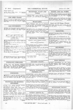
Unique Cross-country Vehicle
Page 54

If you've noticed an error in this article please click here to report it so we can fix it.
A Résumé of Patent Specifications That Have Recently Been Published
ADESIGN, savouring strongly of Continental practice, is described in patent No. 906,831, by P. Riley, of the Riley Engine Co., Ltd, Castle. Works, Coventry Although intended primarily for military purposes, this vehicle is equally suitable for any use involving cross-country work.
The patent describes only the general layout of the design, no mention being made of details, such as steering arrangements and driver's controls. The drawing -shows a partial plan in -which the engine (1) is mounted at one end of the central tubular chassis, whilst -the clutch and gearbox (4) are disposed at the other end, unique accessibility being given as the reason for this unusual practice. The driveshaft from the engine extends the whole length of the chassis to the gearbox, from which the drive is taken forward to the two differentials, via tubular shafts surrounding the primary shaft:
The axles, both of which are driven, are of the swinging half-shaft type, and all wheels are steerable. The suspension arrangements are unusual: each axle is connected to a crank-arm (3) projecting from a frame-supported cylinder (2) containing a screw-andnut mechanism operating in both directions against powerful compression springs. This suspension system has been described in two earlier patents, Nos. 420,433 and 488,172.
Eliminating Backlash in Injection. pumpGovernors.
THE motion of the centrifugal mechanism of an injection-pump governor being small, and the resulting rack-rod movement being comparatively large, it is necessary to ensure that the governor spindle is free from end-play if accurate governing is to be maintained. A governor designed with this in view is shown in patent No. 496,804, by Robert Bosch, G.m.b.H., of Stuttgart, Germany.
In this scheme the injection-pump shaft (6) drives the governor spindle
via spur gears (5 and 4). Springopposed centrifugal weights (3) operate, via bell-cranks, a spindle carrying a collar (2) which moves the rack-rod via a " magnifying " lever system. To eliminate end-play in the spindle, a spring (1), tinder preliminary compression, is .trapped in a central bore and exerts its pressure between the end wall and the spindle, thus keeping the latter at all times pressed up to its bearing. In addition, oil is fed to the spring bore, from which ducts serve to conduct lubricant to the bob-weights and the bell-crank ends.
844 Self governing Injection Pump.
AN -injection pump having a selfgoverning delivery characteristic forms the subject of
patent No. 496,967, which comes from La Precision Mecanique 11, Rue Vergniaud, Paris. This pump, in addition to being provided with the usual helical-edge control, is also constructed to deliver a decreasing quan
OTHER PATENTS OF INTEREST, 496,805 Apparatus for casting-in big-end linings.—F. Ford, Cardin.
496,826 Torsion-bar SuSPension so-stem.-General Motors Corperation, U.S.A.
496,828 Controller for power-operated gearbox.—Maybach-Motorenbau G.m.b.H., Germany.
496,896 Rubber-sprung universal joint.—W. Hamill, Chipman.
496,980 Rubber-assisted suspension system.-A. Dutoonnet, France, 496,983 New design of carburettet.—S.A. Soles, France.
497,026 Starter • pinion meortanism—Robert Desch A.G., Germany.
497,028 Restricted, action differential--R., Meld, Ceeentry.
tity of fuel with an increase of speed.
The plunger bore contains an additional spring-loaded piston (3) bypassed by a passage (1), in which is placed a restriction pin in the form of a setscrew (2). At low speeds all the fuel delivered passes through passage 1, the piston (3) remaining stationary. With an increase in speed, all the fuel has not time to get by, and so some fuel must be provided by displacement of the At the end of the upthe piston is subject only to its spring pressure, and so returns promptly; this leaves a partial vacuum in space 4 which, at high speeds, subtracts its own volume from each succeeding charge. and limits speed.
piston. stroke, Over-run Brake Gear for Trailers.
OVER-RUNNING brake gear for 'L./trailers still comes in for attention, and patent No. 496,923 describes the latest advance in the design of such apparatus. The patentees are A. von Arx, and P. Neidhart, 38, Spitalstrasse, Basle, Switzerland. In this case, the double drawbar is linked to the turntable of the trailer, via a pair of shackles (1) provided with stops to
limit their upward movement. The brake-operating rod is pivoted on the drawbar at point 5 and extends rearwardly to a two-armed lever (4). A central flange (3) on this lever houses a friction-damper, whilstwthe upper end carries the brake rod (2).
Improved Combustion for Small Oil-engines.
ACCORDING to patent No. 496,450, fuel injected in the form of a mist, whilst giving excellent combustion, is inclined to cause harsh running owing to rapid ignition following a delay period. In the design of small engines, mist-injection can hardly be avoided, and the present invention is directed towards reducing the delay period. The patentee is S. A. Adolphe Saurer, Arbon, Switzerland,
The method adopted is to arrange for the injected fuel to mingle with the maximum amount of hot air. This is achieved by commencing injection at about 23 . degrees before top deadcentre. The fuel is thus subjected to a counterblast as the cylinder air is forced into the piston cell, after which, as the piston rises, the injector enters the cell, and injection and combustion are completed in the resulting swirl.


