


Live Axles Tor Commercial Vehicles.
Page 4
Page 5
Page 6
If you've noticed an error in this article please click here to report it so we can fix it.
Further Extracts from the Paper Read before the I.A.E., on Wednesday of Last Week, by Mr. George Watson, Member of Council.
We were unable, owing to considerations of space, to complete the reproduction of our extracts from the paper read by Mr. G. W. Watson entitled "Live Axles for Commercial Vehicles," before the Institute of Automobile Engineers on Wednesday, the 12th inst. The last extract for which we found room in our issue for the 13th January was a paragraph concerning the retention of plain axle bearings. The author thereafter goes on to recall certain accepted figures with regard to the clearances which should be allowed in order to ensure proper efficiency with bushes of this hind.
Floating Bushes.
To ensure satisfactory results with floating bushes, it is necessary that certain conditions should prevail. In the first place both internal and external clearance should be greater than would be allowed for any ordinary bearing; the W.D. specification allows between 6 and 1.3.6 thousandths of an inch for both inside and outside fits, the normal diameters of the bush to which these limits refer being 3i ins. and 4 ins. With too little clearance the distribution of lubrication is uncertain. At least one maker of subsidy vehicles has been persuaded by transport officers to .educe the Clearance to not less than plus 0.004 in. or more than plus 0.006 in., in order to overcome the apparent, play in the wheels when the axle is jacked • up. So far, no ill effect has resulted from the reduction, but it is doubtful whether so little clearance is desirable, either from the point of view of lubrication or the easy removal of the wheels, and it would not surprise the author if the old • allowance is again requested. The play to which objection was made is much more apparent than real.
Proper Lubrication for Axle Bushes.
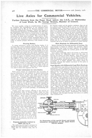
With great reason he emphasizes the necessity of paying attention to the manner in which lubricating • holes and grooves, if any, are made in the bushes themselves. Even to-day, when such points as these receive more studied consideration than was previously the custom, .a number of designers, certainly • many workshop engineers, appear to be content that so long as there are sufficient holes or grooves there is little need to worry as to where they should be located, especially in their relationship to each other. Some comment follows upon the advisability of using steel liners, and, in a later passage, of hardening the wheel journals.
Another point that requires welching is the spacing of the distribution holes in floating bushes; these are best drilled around the bush along a helical line, and they should
be so spaced as to carry grease over every bit of the axle and hub surfaces. Then, again, the rubbing surfates of both axle and hub •should be carefully ground and polished if the best results are to be obtained, and for this reason, unless the' hub of the wheel is a forging, or a very clean and heat-treated
INTERSSEDIATE
mild steel casting, a steel liner should be WA,
forced into the hub under hydraulic pressure, the bore being subsequently ground. Good results have been 'obtained by reamering these liners, but this method was only adopted because of the difficulty of getting rid of the metal particles left in
the oil passageseafter grinding. These reamered liners have given very satisfactory results, but they are not to be recommended in all cases on account of the greater cost of production, due to the wear of the:reamers.
Pressure Intensity Limited to 400lb. per sq. in.
• The author has not found it necessary to harden the wheel journals on an axle, provided that the resultant load, due to C22
the imposed weight and the tractive resistance, does not set up a greater pressure than 900 lb. per sq. in. between axle and floating bush. Such cases of excessive wear on the axles and the bushes which have come to his notice have been duo either to a much higher unit of pressure being allowed, to failure of lubrication owing to the grease passages being too small, or to the use of greases heavily loaded with resinous matter. It might here he noted that the floating type of wheel bearing permits of far greater latitude in the quality of lubricants used than is the case with ball or roller bearings; with the latter it is highly important that the grease should not be a water-carrier, whereas grease containing vegetable fats is by no means so injurious to a plain bearing.
Plain Bearings for Differential Gear.
Before leaving the general question of bearings, the opportunity is taken to discuss the practice, which characterizes the work of some makers, of omitting bronze or other bushes in certain parts of the differential assembly.
Some makers habitually omit. to fit bronze or white-metal bushes between the differential wheels and the cage, or between the pinions and their spindles. Such makers insist that there is no need to do so, and the author's experience leads him to agree with them so long as the oontacting surfaces are hardened, 'ground and polished. Where this is impracticable it is highly desirable tint, bushes should be provided, although the relative movement of the parts is admittedly small.
Good Results with Differential Cage Plain Bearings.
The differential cage itself, as may be seen in several of the illustrations, is most frequently mounted upon ball or roller bearings housed in extensions from the top casing, but in two cases, namely the axles for the subsidy vehicles built by the WoLteley Co. and Wrigley, plain bearings are fitted. Wolseleys favour fixed bronze shells lined with white metal, whilst Wrigleys make use of floating bushes. In each case these plain bushes have been adopted because, at the time the drawings were prepared, it was not found practicable to fit any of the standard sizes of ball bearings specified in the War Office list, which goes to show the foolish policy of setting out arbitrary specifications at so early a stage in design that every requirement cannot be foreseen. The specification left no loophole for designers; they had either to use one of the listed ball bearings or resort to plain bearings. After severe trials with the Wolseley axle, the Mechanical Transport Committee relaxed their view on this matter and gave permission to fit ball bearings of convenient size if desired, but it was then too late to make alterations except of a very costly nature. Furthermore, the results so far obtained with the plain bearings were such as to justify their continued use.
Live Axles (I.A.E. Paper)—con.
A Grumble at Ball-bearing Makers.
We should like to associate ourselves with Mr. Watson's grumble expressed in the paragraph which follows. We ourselves have experienced difficulty in bringing in the radii of these components because of their varialSility.
The author does not here propose to deal with the relative merits of various makes and types of ball bearings. The subject has been dealt with exhaustively in a previous paper le•fore this Institution. He would, however, here like to t xpress his conviction that it is not always necessary to nut up either the inner or .outer races of a ball bearing so long s the shafts are ground to a suitable fit. Ball-bearing niakers lways advocate such nutting Up, but that is probably because el the liberal view they take of limit sizes. The author also takes this opportunity of again expressing an old designer's grumble concerning the small radius which bearing makers grudgingly give their bearings, the amount of which can never he relied upon. Many a shaft is converted into a notched bar, and an otherwise excellent design spoiled, in order to eccommodate a ball bearing with almost square edges.
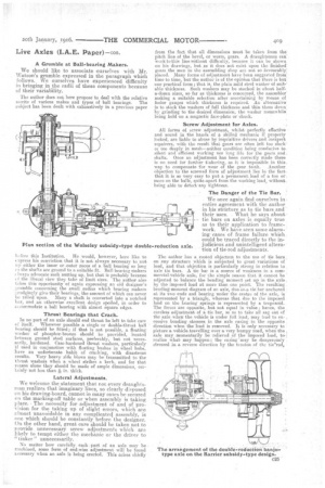
Thrust Bearings that Crack.
In no part of an axle should end thrust be left to take care of itself. Wherever possible a single or double-thrust ball hearing should be fitted; if that is not passible, a floating washer of phosphor-bronze should be provided, located between ground steel surfaces, preferably, but not necessarily, hardened. Case-hardened thrust washers, particularly if used in conjunction with floating bushes in wheel hubs, have an unfortunate habit of cracking, with disastrous results. Very heavy side blows may be transmitted to the thrust washers when a wheel strikes a kerb, and for that reason alone they should be made of ample dimensions, cer
tainly not less than in. thick.
Lateral -Adjustments.
We welcome, the statement that not every draughtsman realizes that imaginary lines, so clearly disposed on his drawing-board, cannot in many cases be secured on the marking-off table or when assembly is taking place. The necessity for adjustment of and of provision. for the taking up of slight errors, which are vbnost unavoidable in any complicated assembly, is one which should be constantly before the designer. On the other hand, great care should be taken not to provide unnecessary screw adjustments which are likely to tempt either the mechanic or the driver to " tinker " unnecessarily.
No matter how carefully each part of an axle may be machined, some form of end-wise adjustment will' be found necessary when an axle is being erected. This arises chiefly
from the fact that all dimensions must be taken from the pitch line of the bevel, or warm, gears. A draughtsman can work to this line without difficulty, because it can be shown on his drawings, but as it does not exist upon the finished' gears the men in the assembling shop are not so favourably', placed. Many forms of adjustment have been suggested from time to time, but the author is of the opinion that there is but one practical form; that is, the plain mild steel washer of suite' able thickness. Such washers may be stocked in about halfa-dozen sizes, so far as thickness is concerned, the assembler' making a suitable selection after ascertaining by means of feeler gauges which thickness is required. An alternative is to stock the washers of full thickness end thin them down by grinding to the desired dimension, the washer meanwhile' being held on a magnetic face-plate or chuck.
• Screw Adjustment for Axles.
All forms of screw. adjustment, whilst •perfectly effective and. sound in the hands of a skilled mechanic if properly locked, are liable to abuse by inquisitive drivers and inexpert repairers, with the residt 'that gears are often left too slack' or too deeply-in 'mesh—neither condition being conducive to silent and efficient working nor lone life for the gears. and. shafts. Once an adjustment has been correctly made there is 'no need for further tinkering, as it is impossible in this. way 'to compensate for wear of the gear .teeth. Another objection to the screwed form of adjustment lies in the fact. that it is so very easy to put a. permanent. load of a ton or, more on the balls, quite.apart from the working load, without: being able to' detect 'any tightness.
The Danger of the Tie Bar.
We once again find ourselves in entire .agreement with the author in his stricture as to tie bars and their uses. _ What he says about' tie bars on axles is equally true as to their application to framework. We have seen some alarm-' ing eases of frame failure which. could be traced directly to the injudiciouS and unintelligent alterstion of tie-rod adjustments.
The author has a rooted objection to the use of tie bars, on any structure which is Subjected to great; variations of load, and that objection is particularly strong in relation to axle tie bars. A tie bar is a source of weakness in a commercial-vehicle axle, for the simple reason that it cannot he adjusted to balance the bending moment set up in the axle, by the, imposed load at more than one point. The resulting. bending-moment diagram of an axle, due, ton tie'bie anchored at its two ends and bearing under the centre of. the axle, is represented by a triangle, whereas that due to the imposed. load on the bearing springs is 'represented by a trapezoid. The forces are opposite, but not equal in value hence, the, careless adjustment of a tie bar, so as to take all sag out of the axle •when' the vehicle is under full load, may lead to ex. , cessive ‘ending -stresses. in the axle easing in the opposite direction when the' lead is removed. It is only necessary to picture a vehicletreVelling over a very bumpy road, when the , axle may -momentarily be 'relieved of theimposed load, to realize what may 'happen; the casing 'may be . dangerously . stressed in a reverse direction by the tension of the tieroci,
Live Axles (I.A.E. Paper)—con,
or, when the load again rests on the axle: the tie rod itself may suffer as a result of the suddenly-inoreased tension. Generally, and as the present conditions in France have shown, it is the tie rod that gives out first, but injury to the axle frequently follows.
An axle should be so designed and made that its strength is sufficient without the doubtful and extraneous aid of a tie rod; that this can be done has been demonstrated by several makers of repute. Considerations of weight, however, as in the case of a London omnibus, more or less force the designer to the use of tie bars, but vehicles with such axles are by no means suitable for country or provincial service, where road surfaces may not be so good as in London, unless they carry greatly reduced loads and are run at lower speeds.
Torque and Thrust.
A useful summary of the various phases of the discussion, which is atill topical, as to the best method of absorbing the torque and the thrust from the driven axle, follows :—
The necessity for some means of transmitting the tractive effort from the axle to the main chassis frame, and for resisting the reaction of the gear drive upon the axle body, or
easing, is obvious. There is, however, great diversity of opinion as to the best means of attaining these results. Some of the tried methods are as follow : (1) A combined torque and thrust member of tubular section, enclosing the card an shaft, and anchored at its forward end by means of a suitable forked or ball and socket connection to one of the cross members.
(2) A torque member of tubular section as above, the tractive effort being taken through the top leaves of the bearing springs.
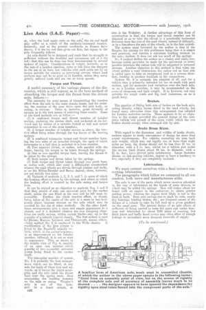
(3) A combined triangular torque and thrust member forming the two sides of an isosceles triangle, the apex of sshich terminates in a ball that is socketed in a cross member.
(4) Two separate thrust, or radius, rods parallel with the frame, leaving the torque to be taken through the springs. (5) One or two parallel torque bars, leaving the thrust to be taken by the springs. (6) Both torque and thrust taken by the springs. • (7) Both torque and thrust taken through two perch bars, or radius rods, which also carry a differential countershaft whence the road wheels are driven through pinions and racks, as on the Milnes-Daimlei and Berne chassis; these, however, are not strictly live axles. (8) Variants of methods 1, 2, 3, 5, and 7, in some of which the braking effort is taken by the springs, and others in which the braking effort is resisted by the axle casing and torque bars.
It can be argued as an objection to methods Nos. 1 and 2 that they permit of only one universal joint for the cardan shaft, unless the one fitted at the rear end be left most in
The triangular member of system No. 3 is probably the best arrangement which can be fitted, at any rate for loads of three tons and upwards, as it leaves the joints accessible and the axle takes the thrust load near the spring seats, thus minimizing the bending moment on the axle or casing. Wrigley's axle is one of this type, and, to a lesser extent, so
C26 also is the Woleeley. A further advantage of this form of construction is that the torque and thrust member can be disposed so as to take the thrust in a practically horizontal direction from the axis of the road wheels, instead of obliquely, or in a lineabove the as of the wheels, as in the first system.
The system most, favoured by the author is that of the Empire, his reasons for this preference being that it is simple and practical, and ensures a minimum bending moment on the axle; farther, it does not ask too much of the springs.
No. 4 method strikes the author as a clumsy and costly one, because unless provision be made for the movement in every possible direction the radius rods will be subjected to torsional stresses. Another objection to this method is that when one wheel strikes a road obstruction the radius rod on that side is called upon to take an exceptional load in a reverse direction, tending to produce backlash in the connections. System No. 6 is certainly the simplest of all, and for a vehicle that is primarily intended for use on roads with good surface, and for moderate load variations over the back axle, as on a 'London omnibus, it may be recommended on the score of cheapness and light weight. It is, however, not very suitable for rough roads and big load variations, as on a goods lorry.
Brakes.
The practice of fitting both sets of brakes on the back axle, acting directly within drums fitted to the road wheels, has found many advocates since this arrangement was adopted for London motorbus service. There appears to be no objection to the system provided the general design of the complete vehicle will permit of the extra width which the two brakes should occupy when arranged side by side.
Brake Drum Sizes.
With regard to the diameters and widths of brake drums, makers appear to study convenience of design far more than actual requirements. For vehicles exceeding six tons back axle weight, which may not legally run at more than eight miles an hour, the drums should not be less than 21 ins, in diameter, with a 3 in. face, whilst for a vehicle just under the six-ton limit drums about 18 ins, in diameter' with a in. face, have Proved quite satisfactory. Large diameter drums, on fast-moving vehicles, appear to have a tendency to fire, especially if they are completely enclosed.
Lubrication.
We must content ourselves with a final extract concerning lubrication. The paragraphs which follow we commend to all our readers, both users, and manufacturers alike.
The axle is one of the parts which never receives attention in the way of lubrication at the hands of some drivers, to which may be added the springs. Men will tinker about for hours with an engine in the endeavour to obtain greater pulling power, whereas the engine most likely is not in the least at fault. Bent axle casings due to slack tie rods, nearly dry bearings, binding brakes. etc., are frequent causes of the failure of a vehicle to take its full load up a given gradient on the usual gear. The general design of an axle allows of sufficient oil being carried to keep the gears and centre bearflgs well lubricated for about 1000 miles of running, but elack joints and badly faced covers may often allow of enough leakage to necessitate more frequent renewals of supply.
(To be continued.)