


Apparatus for Loading Sacks
Page 68
If you've noticed an error in this article please click here to report it so we can fix it.
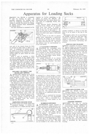
PATENT No. 806,328 is concerned with the loading of sacks. It describes apparatus for loading such items by employing movement of the vehicle to provide the power for lifting. (P. Dunne, Ginnetts Park, Summerhill, Co. Meath, Eire.)
The unit illustrated is mounted on the rear end of the chassis frame by links (1) pivoted at both ends to allow it to rock. It comprises an arcuate 'portion (2) which is in contact with the ground. Rigidly attached to this member is a projecting cradle (3) upon which the sacks are placed.
With a sack inposition, a short forward movement of the vehicle turns the curved member and lifts the sack up and forward to deposit it on the floor.
A short chain (4) is provided to hold the loader clear of the ground when travelling. This operation is assisted by a tension spring (5) which lifts the complete unit when there is no load on the cradle.
MOVABLE FILAMENT FOR HEADLAMP DIPPING
AHEADLAMP dipping device forms the subject of patent No. 806,474 which describes a bulb with a moving filament, the movement being created magnetically. (Joseph Lucas (Industries), Ltd., Great King Street, Birmingham 19.)
The filament is mounted on a pair of springy leads which normally hold it concentrically to produce a horizontal beam.
Moulded into the cap is a strip of iron and the filament support carries a small iron piece also. If the strip is magnetized, it will attract the small piece and so pull the filament away from the central position, causing the beam to dip.
The iron strip can be magnetized by an external winding around the lamp holder, energized from the battery through the dip-switch.
SIMPLIFIED ROCKER GEAR VALVE rockers are usually made from V machined forgings. A scheme for making them as a simple pressing which
requires no further machining is the subject of patent No. 806,176. (N. Momtchiloff and The Austin Motor Co., Ltd., both of Longbridge Works, Bir-. mingham.) The drawing clearly illustrates the proposed form, which can be pressed easily from sheet steel. It works a valve (I) at one end, and receives the thrust of the cam at the point 2. Its other end is formed into a hemispherical socket (3) which seats upon a ball-ended fulcrum (4).
As the rocker is too thin to receive tapped holes, adjustment is performed by altering the height of the fulcrum. To allow this, the ball stud is screwed and fitted with lock-nuts (5). The wearing surfaces may be case-hardened or faced with Stellite.
A VALVE-SEAT GRINDER
/-1 A MACHINE for re-grinding valve. 'seats in situ forms the sublect of patent No. 806,043. The grinding wheel, as it revolves, is also moved around the seat so that it cuts only on line contact. (I, Yule, 145 Yarningale Road, King's Heath, Birmingham, 14.) It consists primarily of an electric motor (1) driving a spindle to which the grinding wheel (2) is attached. The wheel
is enclosed by a sleeve having a conica end (3) which is located by the valve seat Additional location is obtained from a pilot pin (4) which enters the valve guide.
The grinding wheel projects through a cut-away portion of the sleeve to reach the seating. In operation, the wheel runs at 10,000 r.p.m. and the sleeve at about 20 r.p.m. A reduction gear for driving the sleeve comprises a 100 to I epicyclic gear (5) and a 5 to 1 fluid gear located in the space (6). The reduction gear forms the subject of an additional patent numbered 806,044.
Depth of cut is regulated by lowering the motor spindle by a few thousandths of an inch. This is controlled by a knurled knob (7) which pushes on the motor thrust-race.
RUBBER SUSPENSION
A SUSPENSION system claimed to
give satisfactory riding qualities over a wide load range is shown in patent No. 806,077. The resilient medium is stated to be "a resilient plastic of high porosity," but the term rubber will be used for brevity. (V. Pogioli, 50 Via Albertazzi, Bologna, Italy.) Attached to the frame are rectangular metal pots (I) containing blocks of rubber (2). Into these are fitted flanged studs (3) projecting from the axle. The studs are not bonded to the rubber and in the unladen condition, as shown on the left, there is an air space• at the top of the bore.
Rectangular collars (4) are provided in the mouths of the pots and these offer resistance to sideways movement. The scheme is said to be quite suitable for replacing conventional leaf-spring suspension.
SPRINGS FOR TRAILERS
SPRING assemblies for heavy vehicles such as trailers are covered in patent No. 806,312 which describes a method of constructing the eyes of a laminated spring with three full-length leaves at the top. (J. Brockhouse and Co., Ltd., Victoria Works, Hill Top, West Bromwich.)
The drawing shows one end of such a spring. The uppermost leaf (I) is turned over to form an eye (2) to hold a bush. Surrounding the eye is a clip (3) which is pulled downwards by the leaf-retaining clamp (4). The lower end (5) of the clip is V-shaped in plan and extends into a corresponding V-notch cut in the end of the second leaf. The notch also has a short parallel portion to locate the second leaf should it move slightly out of the V portion. The arrangement is said to reduce the tendency for the first leaf to rock on the second one under downward load.
FORWARD-CONTROL CAB
PATENT No. 807,201 comes from Vauxhall Motors, Ltd„ Luton, and discloses improvements in forward-control cabs. The upper part is removable as a complete shell from the lower portion, the dividing line being at or about the waist level of the cab.
LIGHTER STEERING
SUITABLE for use in steering mechanisms and similar applications, a worm-and-nut design described in patent No. 806,811 incorporates ballbearings between the moving members. (George Kent, Ltd., 199 High Holborn, London, W.C.1.) It is said to give a smooth action without back-lash, The thread on the nut is formed by a helical spring, the coils of which act as a bearing race. The balls tend to force the coils apart, but excessive movement is prevented by the -assembly housing.