


Full-circle Equally Loaded Brake-shoe Gear
Page 36
If you've noticed an error in this article please click here to report it so we can fix it.
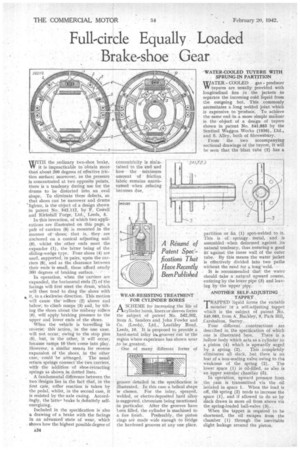
WITH the ,ordinary two-shoe brake, W it is impracticable to obtain more than' about 200 degrees of effective friction surface; moreover, as the pressure is concentrated at two opposite points, there is a tendency during use for the drums to be distorted into an oval shape. To eliminate these defects, so that shoes can be narrower and drums 'lighter, is the object of a design shown in patent No. 542,112, by F. Ceive11 and Kirksia11 Forge, Ltd., Leeds, 5.
• In this invention, of which two applications are illustrated on this page, a parr of carriers (8) is mounted in the manner of slides; that is, they are anchored on a conical adjusting unit (9), whilst the other ends meet the expander (1), the latter being of the • sliding-wedge type. Four shoes (4) are uSed, supported, in pairs; upOn the carriers (8), and as the clearance between their ends is small, these afford nearly 360 degreeS of braking surface.
In operation, when the carriers are expanded, the horizontal ends (7) of the facings 'will first Meet the drain, which will then tend to drag the shoes with it, in a clockwise direction. This motion' will cause tirerollers (2) above and below, to climb ramps (3) and, by tilting the shoes about the midway rollers (6), will apply braking pressure to the upper and lower ends of the shoes.
When the vehicle is travelling in reverse; thiS action., in the one case, Will not occur, Owing to the stop pins (5), but, in the other, it will &cur, because ramps 10 then come into play. However, a similar means for reverse expansion of the shoes, in the other case, could be arranged.' The usual return springs connect the-two carriers., withthe addition of Shoe-retracting springs as shown in. dotted lines. • A fundamental difference between the two designs lies in the fact that, in the first caSe, roller reaction is taken by the pedal; whilst, in the second case, it is resisted by the axle casing. Accordingly, the lattebrake is definitely selfenergizing.
Included in the specification is also a drawing of a brake with the facings in an ad-Vatted state of wear, which shows how the highest possible degree of ASCHEME for increasing the life of cylinder bore's, liners or sleeves forms the subject of patent No. 542,202, from A. Sanders and John Fowler and Co. (Leeds), Ltd., Leathley Road, Leeds, 10. It is proposed to provide a hard metalinlay in., grooves cut itr the regiOn where experience has shown wear ;to be.greatest. ,
One of many different forms of groove detailed in :the specificafon is illustrated. In_ this case a helical shape is chosen. For the inlay, sprayed, welded, or electro-deposited hard alloy is suggested, chromium being mentioned in particular. After the grooves have 1.•een filled, the cylinder is machined to a fine finish. Preferably, the piston rings are made wide enough to 15ridge the hardened grooves at any one place. WATER-COOLED TUYERE WITH SPRUNG-IN PARTITION
WATERCOOLED gas producer VY tuyeres are usually provided with longitudinal fins in the jackets to separate the incoming cold liquid from the outgoing hot. This commonly necessitates a long weldedjoint, which is expensive to .produce. To achieve the same end 'in .,a more simple manner is the object of a design of tuyere shown in patent No. 541,883 by the Sentinel Waggon Works (1936), Ltd,, and S. Alley, both of Shrewsbury.
From the two accompanying sectional drawings of the tayere, it will be seen that the blast tube (2) has a partitionor fin (1) spot-welded to it. This is of springy metal, and is assembled when deformed against its natural tenderity, thus ensuringa good fit against the inner wall of the outer tube. By this means the water jacket is effectively divided into two paths without the need for a long weld.
It is recommended that the water should take a natural upward course, entering by the lower pipe (3) and leaving by the upper pipe.
ANOTHER SELF-ADJUSTING TAPPET
TRAPPED liquid forms the variable member in a self-adjusting tappet which is the subject of patent No. 540,083,, from A. Buckley, 9, Park Hill, Carshalton, Surrey,.
Four different constructions are described in the specification of which one is illustrated here. There is a _hollow body which acts as a'cylinder to a piston (4) which is upwardly urged by a spring (2). This completely eliminates all • slack, but there is no fear of a non-seating valve owing to the weakness of the spring (2). The lower space (1) is oil-filled, as also is an upper annular chamber (5).
In operation, Upward pressure from the cam is transmitted via the oil isolated in space 1. When the load is off, fife spring (2) tends to increase the space (1), and if allowed to do so by slack draws in more oil from above via the spring-loaded ball-valve (9).
When the tappet is required to be shortened, the oil escapes from the chamber (1) through the inevitable slight leakage around the piston.