


THE CONTROL OF TRANSPORT BY WIRELESS.
Page 13
Page 14
If you've noticed an error in this article please click here to report it so we can fix it.
In this Third Article Upon the Application of Wireless Telephony to the Control of Transport, We Deal with Some Detail Components Most Suitable for This Special Purpose.
IN THE LAST two issues of The Commercial if otor we have touched upon the fundamentals of wireless telephony, and have shown what it can do and how it can be employed in controlling the operations of a transport vehicle—not2 of course, as affecting its mechanical control, but in instructing the driver as to where and when to call for a load or to deliver the whole or a portion of the load carried by his vehicle. The ability so to alter the destination of a vehicle after it has left its base will be of enormous value to owners and users of road transport vehicles.
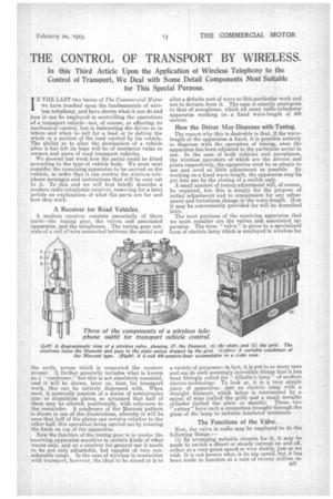
We showed last week how the aerial could be fitted according to the type of vehicle body. We must next consider the remaining apparatus to be carried on the vehicle, in order that it can receive the wireless telephone messages and instructions that will be sent out to it. To this end we will first briefly describe a modern radio-telephonic receiver, reserving for a later article an explanation of what the. parts are for and how they work.
A Receiver for Road Vehicles,
, A modern receiver consists essentially Of three parts—the tuning gear, the valves and associated apparatus, and the telephones. The tuning gear consists of a coil of wire connected between the aerial and the earth across which is connected the receiver I proper. t further generally includes what is known as a" condenser," but this is not absolutely essential, and it will be shown, later on that, for transport work, this can be entirely dispensed with. When used, it generally consists of a series of semicircular zinc or aluminium plates, so arranged that half of them may be altered, positionally, with reference to the remainder. A condenser of the Marconi pattern is shown in one of the illustrations, whereby it will be seen that half of the plates can revolve relative to the other half, this operation being carried out by rotating the knob on top of the apparatus.
Now the function of the tuning gear is to render the receiving apparatus sensitive to certain kinds of ether waves only, and on a receiver for general use it needs to be not only adjustable, but capable of very considerable range. In the case of wireless in connection with transport, however, the ideal to be aimed at is to allot a definite sort of wave to this particular work and not to deviate from it. The case is exactly analogous to that of aeroplanes, which all carry radio-telephony apparatus working on a fixed wave-length of 900 metres.
How the Driver May Dispense with Tuning.
The reason why this is desirable is that, if the wavelength of the apparatus is fixed, it is possible entirely to dispense with the operation of tuning, once the apparatus has been adjusted to the particular aerial in use. In the case of both vehicles and aeroplanes, the wireless operators of which are the drivers and pilots respectively, the apparatus must be as simple to use and need as little adjustment as possible. By working on a fixed wave-length, the apparatus may be put into use by the closing of a switch only.
A small amount of tuning adjustment will, of course, be required, but this is simply for the purpose of initial adjustment and to compensate for any subsequent and fortuitous change in the wave-length. How it may be conveniently provided for will be described later.
The next portions of the receiving apparatus that we must consider are the valves and associated apparatus. The term " valve " is given to a specialized form of electric lamp which is employed in wireless for a variety of purposes—in fact, it is put to so many uses and can do such seemingly incredible things that it has been fittingly called the " Alladin's lamp" of modern electro-technology. To look at, it is a very simple piece of apparatus : just an electric lamp with a straight filament, which latter is surrounded by a spiral of wire (called the grid) and a small metallic cylinder (called the plate or sheath). These two extras" have each a connection brought through the glass of the lamp to suitable insulated terminals.
The Functions of the Valve.
Now, the valve in radio may be employed to do the following things :—
(1) By arranging suitable circuits for it, it may be made to switch a direct or steady current on and off, either at a very great speed or very slowly, just as we wish. It is not known what is its top speed, but it has been made to function at a rate of twenty million in terruptions a second quite successfully. Since., as we pointed out in the first article of this series, it is by interrupting a current that we are able to jog the other, this is how the valve is employed for transmission purposes.
(2) It may be employed as a detector of wireless signals ; that is, it may 'be made to translate the ether jogs of which our messages are composed into something that the telephones can turn into sound. How it does this will be explained later.
(3) It may be used to amplify, and in tans case it becomes a very delicate form of electrical relay—far more sensitive than any mechanical relay that we could devise, and having, moreover, the great advantage that it has no moving parts.
The Filtering Action of the Valve.
Without going into too much detail at present, it may be explained that the valve functions by making use of those spare electrons, with which, as we stated. all conductors are supplied. It has been found that, when we heat any conductor in a vacuum, the electrons become loosened from its surface and start to take little walks out into the surrounding ether (be cause, of course, when we pump all the air out of a space, such as an electric lamp bulb, we do not disturb the contained ether). The number of electrons that leave in this way depends on the temperature to which we heat the conductor ; the higher the temperature, the larger the number of electrons. In the case of the ordinary electric lamp, the electrons, having proceeded a short distance, fall back again on to the filament. But if we have, inside the lamp, a plate of metal that can be connected to an outside source of positive electricity, then,. since electrons are really units of negative electricity, and since a positively charged body is one with a deficiency of electrons, the electrons emitted from the heated filament -will go straight to the plate, or, in Other, and common, electrical language, a current will travel across the vacuum from the plate to the filament.
If, moreover, we also have, inside the lamp and between the filament and the plate, a spiral, or wire mesh, grid, then we shall find that, if we electrify this grid negatively, it -will prevent electrons from reaching the plate, however positive we make this latter, while, if we electrify the grid positively, it will assist the electron stream on its way to the plate. It will thus be seen that the grid allows us to control exactly the amount of current that will travel through the valve, and by suitable design the current so controlled
in the plate circuit can be several hundred times as great as the current needed to operate on the grid.
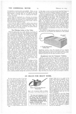
Valves are made in a variety of forms and sizes, and several are illustrated here. For reception they take about f ampere at 4 volts to heat the filament, and from 30-90 volts on the plate. For transmission they are much larger and require up to 8 amperes at 12 volts for the filament and 1,500 to 2,000 volts on the plate. In reception, they may he used in cascade— that is, the output from one valve may he made to operate the grid of a second, and so on—if the amplification obtained from one valve is not sufficient. For a transport receiver, for reasons that will appear later, we shall require at least four valves, and, therefore, we shall need an accumulator of from 60 to 80 amp.hours capacity.
As a source of high-tension current for the plates of the valves we can employ dry batteries of the pocket flashlamp variety, since the amount of h.-t. current taken, even by four valves, is extremely small. These may be had made up into 15-volt units, and, with care, will give good service for three months or more.
Headphones best for Transport Vehicles.
Lastly, we come to the telephones, and these do not differ materially from the ordinary pattern known to everybody, except that they are more carefully made and are far more sensitive. They are of two patterna —headphones, which consist of two watch receivers fastened to a headband so that they may be worn and leave the operator's hands free ; and loud-speakers, which consist of a single telephone with an extra big diaphragm and fitted with a horn something like a gramophone. Since the last-mentioned need much more energy than do the headphones to operate them, they will not, as a rule, be used on transport vehicles.