


SPRINGS FOR MOTOR VEHICLES.
Page 16
Page 17
Page 18
If you've noticed an error in this article please click here to report it so we can fix it.
An Inquiry into the Effect of Using the .Spring to Transmit the Torque and Thrust.
HE RECENT discussion in the pages of THE COMMERCIAL MOTOn relative to the use of rear springs to transmit torque and thrust has evokod some interesting opinions on the important subject,of spring suspension. From the point of view of simplicity and cheapness, it is very desirable to employ the springs for this purpose, but, as this is a secondary .function of the springs, its utility .depends upon whether it interferes with the primary function of shock absorption.
The development of spring design has been mainly an evolutionary process, the comfort of passengers and drivers, immunity from damage of the goods transported and the minimization of depreciation of the chassis parts being the governing factors. One of the main features in the development has been in gradually increasing the length of the springs and decreasing the camber. Another feature is the attempt made to produce an automatic adjustment of the springs according to the varying weight of the load carried, for it is quite obvious that springs suitable for a vehicle when fully loaded will be too stiff when the vehicle is unloaded: An auxiliary development is the application of shock absorbers.
As already stated, the primary function is to prevent shocks, by damping out the vibrations, caused by blows on the wheels when travelling over uneven ground. Or, it may b—e stated, that the springs lengthen the time of the blows and, therefore, diminish the average force of the blows. Certain types of springs also possess another valuable feature, which consists of absorbing part of the force of the blow in the spring itself by converting Part of the kinetic energy of motion into heat energy of friction. Laminated springs possess this property in the greatest degree, hence the universal adoption of this
• type for motor vehicles. The kinetic energy of the vibrating mass supported by the springs is gradually converted into heat energy by the friction between the plates.
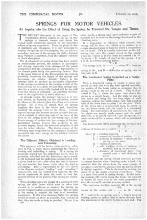
• The Different Effects Obtained in Loading and Unloading.
• This property will be better understood by reference to Fig. 1, which shows graphically the effect of loading and unloading a spring. If a spring be • gradually loaded and the deflections noted, then be gradually unloaded and the defleetions again noted, it will be found that the deflection corresponding with a given load has one value when the load is increasing and another, but lesser, value when the load is decreasing.. This is represented by the two curves in the diagram marked " loa.d,jng" and " unloading " respectively, and the shaded area between the two curves represents to scale the work in inch lbs. against 'friction of the plates of the spring per oscillation.
When deciding upon the design of a laminated steel spring, the chief factor which must be taken into account is its resilience or capacity for storing up energy without taking a .permanent set. The strength of the spring to support the load is of secondary importance. If this were the-main factor the springs would be made as short as possible, but, instead of that, they are made as long as possible. To put it in other words, a spring must have sufficient weight of material in it to store up the energy developed by the vibrating parts.
It is impossible to calculate what amount this energy will be when the vehicle is in motion, So a Certain standard must be fixed by which a comparison eau he made. This s Usually calculated at the following rate, viz., the energy stored in, the spring when the vehicle is at rest must not exceed 5 ft.. Da. for every 1 lb. weight. of steel in the spring ; 3 or ti ft. lb. is a better average figure.
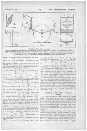
Now, a laminated spring is simply a beam supported at each end with the lead applied centrally, the section of the beam being so arranged that it always bends to the are of a circle. This is illustrated, in Fig. 2, where the upper view shows the spring as a simple beam. Let the plate be cut up into strips and bring the two long edges of each together, making full width plates, each with pointed ends of the same form as plate 1 on the plan. Pack all the strips into a symmetrical heap, as shown in the two lower views, and the result is a laminated spring. For convenience of manufacture the ends of the plates are usually made square and the small plate (No. 5) is usually omitted ; also the springs Are made cambered for a reason which will be described later.
In order that the spring should correctly perform its proper function when vibrating :under a load, it is essential that the plates have the same change of curvature everywhere, and also that the plates always fit tightly together: This is obtained by making the stress (f) in the plates constant everywhere. This is a most vital point in spring design. •As the bending moment (M) varies along the beam, the moment of inertia (I) must vary in the same proportion tf keep the stress (f) constant at. every section.
The MAXIMUM bending moment (M) in the spring W – load in lb. on spring, and L = length between bearing points • in inches, and it varies directly from this maximum at the eentre to zero at each end. The moment Of inertia (I) of a plate of width B ins, thick ness t ins. = — in. moments. Therefore, to keep 12 the' stress (f) constant, the breadth (B) mast vary directly from maximum at the centre to zero at each end. By referring to Fig. 2 it is quite obvious that a laminated spring fulfils this condition.
which shows that the thickness of spring plates depends upon the span (L), the total deflection desired (d), the safe working stress (0, and the modulus of elasticily (E); and it is independent of the load to be carried.
Instead of varying the width, the plate is cut into equal widths, and the pieces placed under each other, as shown in Fig. 2. Then, if b = width of each plate in inches. and n number of plates, b n =" B, and Deets the load to be carried with the number of plates and their width. There is a stress f ▪ due to the static load W, and an additional stress ± fo due to the vibrations. Therefore, the total stress ft = f + fo. The additional stress fo will cause ad additional deflection do ; d, (f + fo) fi d then = and fi — , where f + fo d + do d ell= the total deflection due to both static load and vibiations.
The total stress f1) should be the values used in the above equations but as (do) and (fo) cannot be calculated, the only way,is to allow for this by taking a low figure for the stress (f), which has already been done. The actual safe working stress of spring steel is approximately 130,000 lb. per sq. in.
Strictly speaking, these only apply when the spring is derived from the single triangular plate, as in Fig. 2, but the differences, due to manufacturing variations, previously described, are so small that they can be ignored. If, however, the spring is hooped in the centre, the hoop renders part of the spring inoperative, and the effective length (L) should be taken as the total length between bearing points—half tha width of the hoop.
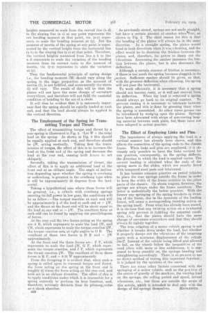
The above calculations are all based on the spring being evenly loaded at each end, as illustrated in Fig. 3. If the forces are not equal on each side, then it iS obvious that the stress in the'material will not be eonstant everywhere in the plates. Therefore, the change of curvature will not be conatant everywhete. Thus, the essential condition will not be fulfilled anil, consequently, the action of the spring will be seriously impaired.
Again, if the forces acting on the ends of the springs are not vertical, a, further variation is caused, as shown in Fig. 4. The horizontal component Wh of the force W produces a bending moment in the opposite direction to the vertical component_ Therefcre, the bending moment and the deflection are reduce-d towards the centre of the spring. Vertical heights measured -be scale from the curved .line d) to the sloping line (a c) at any point represents the net bending mernent at that point, viz. (x-y) repreRents to scale the bending moment at (y). But the moment of inertia of the spring at any point is repreRented by the vertical height from the horizontal line (a b) to the sloping line (a e) at that point. Therefore, the vertical heights measured from line a b line a d represents to scale the variation of the bending moment from_ its correct ratio to the moment of inertia, viz. (y z) represents to sale the variation at (y).
Thus the fundamental principle of spring design i.e., the bending moment (111) should vary along the spring in the same proportion as the moment of inertia (I), is not fulfilled, and consequently the stress (£) will vary. The result of this will be that the plates will not have the same change of curvature everywhere, and therefore will not fulfil the essential :condition of bending to the are of a circle.
It will thus be evident that it is extremely important that the spring should be equally leaded at each end, and that the load should always be applied in the vertical dieection.
The Employment of the Spring for Transmitting Torque and Thrust.
The effect of transmitting torque and thrust by a rear spring is illustrated in Fig. 5. -Let W = the total load on the spring. As shown in Fig. 3 this should be equally applied at each end, and therefore should be W, acting vertically. Taking first the transmission of torque, the effect of this is to increase the load at the front end of the spring and decrease the load at the rear end, causingboth forces to act obliquely: Secondly, taking the transmission of thrust, the effect of this is to apply an additional load at the front end at an oblique angle. The angle of inclination depending upon whether the spring is overhung or underslung, is greatest in the overhung type when it will be approximately 20 degrees from the horizontal.
Taking a hypothetical case where these forces will be greatest, i.e., a vehicle with overhung springs exerting its full power in low gear, the conditions will be as follow :—The torque reaction at each end will be approximately of the load at each end or = and the thrust at the front end will be about equal to the load at one end or = W. The resultant force at each end can be found by applying the parallelogram of forces.
At the rear end the two forces acting on the spring are A B, which represents to scale the load 4W, and OB, which represents to scale the-torque reaction 1W, the torque reaction acts at right angles to 0 B. The resultant of these two forces is P B .and = 43W approximately.
At the front end the three forces are : E F, which represents to scale the load 4W, G F, which represents the torque reaction, and J F, which represents the thrust reaction W. The resultant of these three forces is K F, and = 9-10 W approximately.
From the foregoing it is evident that, when such a spring is called upon to transmit torque and thrust, the force acting on the spring at the front end is roughly 24 times the force acting on the rear end, and both act in an oblique directlon. ' The effect of this is to apply conditions under_ which it is impossible for a spring correctly to perform its true function, and, therefore, 'seriously detracts from its primaryevalue .a. shock absorber.
038 As previously stated, springs are not made straight, , but have a certain amount of camber when4ree, as' .shown in Fig. 3. The chief reason for this is that the bending of the plates will always be in the same.
direction. In a straight spring, the plates would bend in both direction e when it was vibrating, and the effect would be to decrease the friction between the plates, and, therefore, its power to damp out the vibrations. Increasing the camber increases the friction between the plates, but it also decreases .the deflection.
Although a certain amount of friction is necessary, if there is too much the spring becomes sluggish in its , action. Sufficient camber should We given, so that, with the greatest deflection when vibrating, the spring will not pass the horizontal.
To work efficiently, itis necessary that a. spring should not 'become rusty, or it will not recover from its deflection. When the load is removed a Spring should always go back to its original camber.. To, prevent rusting it is necessary to lubricate betereen• the plates, and this is done by -greasing them when the spring is assembled. At other times grease can he introduced by wedging open the plates. Springs have been advocated with strips of non-rusting bearing material between each plate, but these have not been adopted in actual practice.
The Effect of Employing Links and Pins.
. The importance -of always "applying the load in a vertical manner has already been shown, and this affects the connection of the spring ends to the chassis frame. When links and pinsare employed, it is obviously only possible to have the links vertical for one position, consequently, as the spring deflects, the direction in which the load is applied varies. The correct loading is Obtained when the ends of the spring move. in flat slides, which are usually fitted with tempered steel pads and lubricated.
It has become common practice On petrol vehicles to place the rear springs outside the frame in order to keep the width of the frame suitable to the _other parts of the chaseis. On steam wagons, however, the springs are always under the frame members. The latter is undoubtedly the better practice. With the former any springing of the spring brackets or twisting of -the frame, due ten the moments of the loading forces, will cause a corresponding twisting action on the spring itself. From what has already been stated, it is obvious that any twisting .aetion on a laminated spring will prevent it -fulfilling the essential condition, i.e., that the plates should have the same change of curvature everywhere and that they should always fit tightly together.
' The true criterion of a motor vehicle spring is not whether it-breaks down 'under the load, but whether it properly damps out the vibrations of the unsprung parts with a minimum displacement of the vehiele itself. Instead of the vehicle being lifted and allowed to fall, as the wheels follow the inequalities of the road often with more or less suddenness, it is supposed to keep _steadily on, the springs bending and straightening accordingly. There is at present.in use no direct method of testing this important function; it is judged by the opinions of the users.
There are many other factors concerned with the' springing of a motor vehicle, such as the pos'tion of the centre of gravity of the machine, the varying load on the springs, the rolling period and speed, lateral vibrations, etc., but these are outside the scope of this article, which is intended to deal only with the design of the -springs themselves. REM/MITS.