


Patents Completed.
Page 28
If you've noticed an error in this article please click here to report it so we can fix it.
UNIVERSAL JOINT.—Fowkes.--No. 16,555, dated 19th July, 1907.—This joint is of the type wherein tapered, or Vshaped, teeth are employed on the engaging portions of two shafts with which a universal movement is required. The shaft (B) carries a head on which a series of radially-disposed, wedge-shaped teeth (81.) are formed ; these teeth, in addition to being wedge-shaped, are concave, and receive convex, wedge-shaped teeth (al) carried by the shaft portion (A). A hard steel ball (C) provides a pivot whereon the shaft (A) rolls relatively to the shaft 113). The head of the shaft (13) carries a cap (E) provided with a screw-threaded, retaining ring (el). On that part of the shaft (A) within this ring is a head (a2) which engages the ring, the engaging parts being concaved and convexed respectively. The teeth (al) are carried by a block that is free to slide to the head (a2) ; these teeth can be adjusted by means of screws (F). These screws have squared ends (p) that enter sockets in the head (a2) ; the screws also carry nuts (11)
whereby the block carrying the teeth (al) can be advanced, or withdrawn, relatively to the shaft portions (A, B).
CLIP FOR FLEXIBLE HOSE.Craig.—No. 1,298.—Dated 18th January, 1907.--This clip comprises a strip of resilient metal having a series of corrugations, or teeth, at one end, and a single tooth, or claw, at the other. end. The single claw is disposed on the opposite end of the strip to that occupied by the series of teeth. In use, the strip is bent round the hose after it has been placed over the metal pipe, and the length of the clip is such, that the claw will then overlap the teeth. A hole is provided in that end of the strip that carries the claw in order that a lever may be inserted for the purpose of prising the claw forwards over the teeth. The clip can thus be made to grip the hose with very considerable force and so secure it in place.
VALVE GE AR.—Raky.—No. 11,051, dated 11th May, 1907.—This invention relates to valve actuating gear of the type in which an oscillating member transmits motioia to a lever, the motion being then transmitted to the valve required to be actuated. The shaft (a) is provided with an arm (b), the latter being connected to combined cam and lever members (d, d1) by means of links (c, el). These cam and lever members are attached to the spindles (e, el) on their other ends. A disc (f) is arranged between the cam levers (d, di); it is loosely mounted, and rotates on the shaft (a), and is prevented from shifting on the shaft by means of collars. This disc is so placed between the cam levers (d, that, when an oscillatory, or rock ing, motion is given to the motor shaft (a) in one, or another, direction, the cam levers (d, dl) are pressed against the disc (f), whereby the disc serves as a rest, or a fulcrum, alternately, for one, or the other, cam lever, so that each acts as a double lever with a varying, or shifting, fulcrum. Those edges of the cam levers (d, d1), which are adjacent to the disc (f), are curved (as at g). This curve takes a short turn at al, whereby a protuberance, or cam (g1), is formed. When the shaft (a) turns, the lever arm (b) begins the downward motion, and the curved part (g) of the uppermost cam lever (d) rolls upon the disc (f), the cam lever (d), meanwhile, acting as a double-arm lever having a moving fulcrum on the circular disc. The spindle (e) is thus slowly lifted by this motion, owing to the short lever arm to the left of the fulcrum, and to the shape of the edge, the rate of lifting being maintained until the point (A comes into contact with the disc (f). Now the spindle (e) is lifted, the protuberance (gl) being the fulcrum. At this stage of the operation the lifting is rapidly accelerated. Thus, the lifting of the valve is slow at the commencement, but, during the real opening of the valve, it is rapidly accelerated.
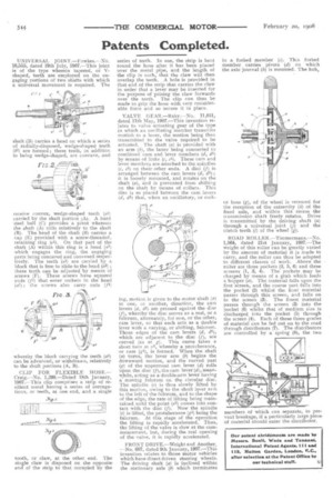
FRONT DRIVE.—Wright and Another. --No. 607, dated 9th January, 1907.—This invention relates to those motor vehicles which have direct driven steering wheels. The driving shaft (a) is inclined within the stationary axle (b) which terminates in a forked member (c) . This forked member carries pivots (d) on which the axle journal (h) is mounted. The hub, or boss (g), of the wheel is recessed for the reception of the extremity (h) of the fixed axle, and within this recess the transmission shaft freely rotates. Drive is transmitted by the driving shaft (a) through a universal joint (j) and the clutch teeth (1) of the wheel (g).
ROAD ROLLER.—Timmermans.—No. 1,564, dated 21st January, 1907.—The weight of this roller can be greatly varied by the amount of material it is made to carry, and the roller can thus be adapted to different classes of work. Above the roller are three pockets (2, 5, 6) and three screens (1, 3, 4). The pockets may be charged by means of a grab which feeds a hopper (a). The material falls upon the first screen, and the coarse part falls into the pocket (2) whilst the finer material passes through this screen, and falls on to the screen (3). The finest material passes through the screen (3) into the pocket (6) whilst that of medium size is discharged into the pocket (5) through the screen (4). Each of these three grades of material can 'be fed out on to the road through distributors (7). The distributors are controlled by a spring (8), the two
members of which can separate, to prevent breakage, if a particularly large piece of material should enter the distributor.