


Three-plus-one truck transporter
Page 29
If you've noticed an error in this article please click here to report it so we can fix it.
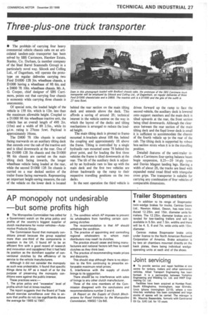
• The problem of carrying four heavy commercial vehicle chassis cabs on an articulated tandem-axle transporter I has been solved by SBS Carrimore, Harelaw Estate, Stanley, Co. Durham, (a member company of the Steel Barrel Scarnmells Group) in a particularly novel way. Silcock and Coiling Ltd., of Dagenham, will operate the prototype on regular deliveries carrying two Ford D1000 12ft 3in. wheelbase chassis, a D1000 having a wheelbase of 9ft 6in. and a D800 7ft 10in, wheelbase chassis. Mr. A. G. Cooper, chief designer of OS Carrimore, points out that carrying four chassis is economic while carrying three chassis is uneconomic.
Of special note, the loaded height of the vehicle is 15ft 6m. which is 12in. less than the maximum allowable height. Coupled to a Dl 000 9ft bin wheelbase tractive unit, the vehicle has an overall length of 49ft 2in. (15m) and a width of 8f1 2.5in., while its g.t.w. rating is 27tons 5cwt. Payload is approximately 16tons.
The D800 7f1 10in chassis is carried facing rearwards on an auxiliary tilting deck that extends over the cab of the tractive unit and is tilted downwards at the rear. One of the 1)1000 12ft 3in chassis and the D1000 9ft 6in chassis are carried on the main tilting deck facing inwards, the longer wheelbase vehicle being loaded at the rear, while the second 131000 12ft 3in chassis is carried on a rear decked section of the trailer frame facing rearwards. Representing an important height-saving measure, the cab of the vehicle on the lower deck is located behind the rear section on the main tilting deck and extends above the deck. This affords a saving of around 2ft; technical interest in the vehicle centres on the way in which the layout of the decks and tilting mechanisms is arranged to reduce the loaded height. The main tilting deck is pivoted to framemounted A-brackets about 10ft 6in. behind the coupling and approximately 1ft above the frame. Tilting is controlled by a single hydraulic ram mounted some 7ft behind the pivot' point, and for loading the first three vehicles the frame is tilted downwards at the rear. The tilt of the auxiliary deck is adjusted by• an hydraulic ram to line up with the main deck and the first two vehicles are driven backwards up the ramp to their respective travelling positions on the two decks.
In the next operation the third vehicle is
driven forward up the ramp to face the second vehicle, the auxiliary deck is lowered Onto support members and the main deck is tilted upwards at the rear, the front section being tilted downwards. Although the clearance between the rear section of the main tilting deck and the fixed lower deck is small it is sufficient to accOmmodate the Chassis of the fourth vehicle up to the rear of the cab. The tilting deck is supported by robust box-section struts when it is in the travelling position.
Detailed features of the semi-trailer include a Carrimore four-spring balance beam bogie suspension, 8.25-20 14-ply tyres and Davies Magnet landing legs. Having a width of about 2ft, the tracks are lined with expanded metal tread fitted with triangular cross grips. The transporter is suitable for carrying any combination of four vehicles of comparable dimensions.