


Improved Rear Vision
Page 60
If you've noticed an error in this article please click here to report it so we can fix it.
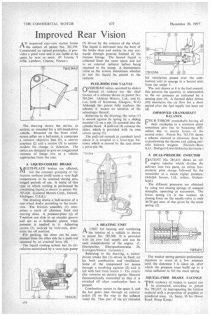
A N improved rear-view mirror forms the subject of patent No. 785,359. Constructed on optical principles, it provides a good view and is not liable to be upset by rain or snow. (P. Jouvin, 5 Villa Lambert, Chatou, France.)
The drawing shows the device, in section, as intended for a left-hand-drive vehicle. Mounted on the front windscreen pillar on a ball-joint, it comprises a concave objective lens (1), a convex eyepiece (2) and a mirror (3) to accommodate the change in direction. The optics are designed to give an exaggerated increase of image size as a vehicle approaches from the rear.
A LIQUID-COOLED BRAKE MULTI-PLATE brakes are efficient, but the compact grouping of the friction surfaces could cause a very high temperature to be attained during pro: longed periods of use. A brake of this type in which cooling is performed by circulating liquid, is shown in patent No. 785,426. (General Motors Corp., Detroit, Michigan, U.S.A.) The drawing shows a half-section of a rear-wheel brake according to the invention. . The friction assembly (1) comprises a stack of alternate fixed and moving discs. A pressure-plate (2) of T-section can slide in an annular groove and act as a hydraulic piston when pressure is applied to ' it. Adjusting screws (3), secured by lock-nuts, determine the off position.
For parking, the discs can be compressed from the other side by a push-rod operated by an external lever:(4).
The: liquid cooling system has its circulation maintained by a vane-type pump (5) driven by the rotation of the wheel. The liquid is delivered into the bore of the brake discs and makes its way outwards through grooves formed in the friction linings. The heated liquid is collected from the outer space and led to an external radiator before being returned to the pump. A thermostatic valve in the system determines whether or not the liquid be passed to the radiator.
PULL-RODS FOR VALVES OVERHEAD valves operated by sliders instead of rockers are the chief feature of a scheme shown in patent No. 785,244. (Albion Motors, Ltd., and G. Lee, both of Scotstoun, Glasgow, W.4.) Although the patent fully explains the scheme; it makes no mention of the advantages thereof.
Referring to the drawing, the valve (1) is moved against its spring by a sliding member (2) on a pin (3) screwed into the cylinder-head. A pull-rod (4) actuates the slider, which is provided with its own return spring (5).
The pull-rod extends to camshaft level where it is coupled to a lever-type follower which is moved by the cam about a pivot-pin (6).
A HEATING UNIT A UNIT for heating and ventilating 1-1 the interior of a vehicle is shown in patent No. 785,288. It is provided with its own fuel supply and can be used independently of the engine. (I. Eberspacher, Eberspacherstrasse 24, Esslingen/Neckar. Germany.) Referring to the drawing, a motordriven intake fan (I) draws in fresh air for both combustion and ventilation. Some of the compressed air passes through a revolving agitator (2), and is fed with fuel from nozzle 3. The nozzle also contains an electric igniter filament thermostatically controlled so that it is switched off when combustion heat is present.
Combustion occurs in the space 4, and the hot gases pass through an annular jacket (5) on the way to the exhaust outlet (6). That part of the air intended for ventilation passes over the combustion unit to emerge in a heated state from the outlet 7.
The unit shown at 8 is the fuel control; this governs the quantity in relationship to the air pressure as indicated by a sensing pipe (9). A thermal delay device (10) maintains the air flow for a short period after the fuel supply has been cut off.
IMPROVED CRANKSHAFT BALANCE FOUR-THROW crankshafts having all their crankpins in a common plane sometimes give rise to balancing difficulties due to inertia forces of the second order. Patent No. 785,518 shows a scheme claimed to eliminate these by re-positioning the throws and adding suitable balance weights. (Daimler-Benz A.G., Stuttgart-Untertilrkheim,Germany.) A DUAL-PRESSURE INJECTOR PATENT No. 785,411 shows an oilengine injector which divides the delivery into two parts, an initial lowpressure pilot charge followed by the remainder at a much higher pressure. (Adolph Saurer, Ltd., Arbon, Switzerland.)
The different pressures are obtained by using two closing springs of unequal strengths, operating in succession. The lower spring (I) is the weaker; its closing force on the needle-valve is only 30-70 per cent, of that given by the main spring (2).
The weaker spring permits preliminary injection to occur at a low pressure until the clearance 3 is taken up, after which the pressure must build up to a value sufficient to lift the main spring.
SQUEAL-FREE BRAKE FACINGS 'THE tendency of brakes to squeal can I be eliminated, according to patent No. 785,615, by impregnating the friction material with a proportion of graphite or powdered mica. (A. Samy, 10 Ice House Road, Hong Kong.)