


A New Injection System for Oil Engines
Page 52
If you've noticed an error in this article please click here to report it so we can fix it.
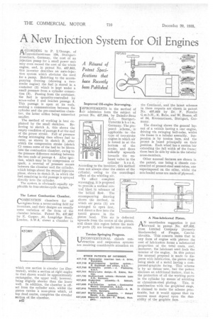
ACCORDING to P. L'Ora.nge, of 1--Canzistatterstrasse 130, . StuttgartF,euerbach, Germany, the cost of an injection pump for a small power unit may even exceed the cost of the whole engine, and, in patent No. 437,853, this inventor describes an auto-injection system which obviates the need for a pump. Referring to the accompanying drawing (showing a twostroke engine) the fuel is stored in a container (2) which is kept under a small pressure from a cylinder connection (3). Passing from the container, the fuel is quantity-controlled by screw-valve 1 and reaches passage 5. This passage is open at its ends, making a communication between the cylinder and the pre-combustion chamber, the latter orifice being somewhat smaller.
The method of working is best ex
plained by the small sketches. Referring to sketch A, this shows the empty condition of passage 5 at the end of the power stroke. Fall of pressure during scavenging then allows fuel to enter, as shown in sketch B, after which the compression stroke (sketch C) causes some of the fuel to be blown into the combustion chamber, owing to the pressure difference existing between the two ends of passage 4. After ignition, which may be by compression or spark, a reversal of pressure occurs between the chamber and, the cylinder, which brings about the second injection phase, shown in sketch D, in which the fuel remaining in the passage is sprayed directly into the cylinder.
The system is obviously. equally applicable to four-stroke-cycle engines.
The Latest Combustion Chamber.
COMBUSTION chambers for oil ..engines form a never-ending field for inventors, and their designs are usually some variation of the form of the chamber interior. Patent No. 437,887 by E. Gaspar, .44, Longridge Road, London, S.W.5, shows a chamber in which one section is circular (as illustrated), whilst a section at right angles to that shown would be approximately rectangular, the upper wall,however, being slightly shorter than the lower wall. In addition, the chamber is offset from the cylinder axis, whilst the piston carries a nose-piece which, at top dead centre, completes the circular section of the chamber.
B42
Improved Oil-engine Scavenging.
pIPROVEMENTS in the method of Iair admission form the subject of patent No. 437,584, by Daimler-Benz A.G„ StuttgartUnterttir khei m, Germany. The proposed. , scheme, is applicable to the type Of two-stroke engine.in which air is forced in at the bottom • of the stroke, and flows helically upwards towards the exhaust valve in the
cylinder h e a d. According to the inventor, this method does not always clear the centre of the cylinder, owing to the centrifugal effect of the whirling air.
To effect complete scavenging, it is proposed to provide a vertical central blast in adVance of the helical Ito*. The accompanying drawing shows the method, in which air ports (1) are arranged to open first, and direct a flow into the toroid groove in the piston head. This air, is deflected upwards from the centre of the piston, and clears this region before the main air ports (2) are brought into action.
Torsion Springing Progress.
UNCONVENTIONAL chassis construction and suspension systems are receiving considerable attention on
the Continent, and the latest schemes in these respects are shown in patent No. 437,633 by Dr. F. Porsche G.m.b.H., K. Rabe, and W. Boxan, all of 24, Kronenstrasse, Stuttgart, Germany.
The drawing shows the general layout of a vehicle having a rear engine, driving via swinging half-axles, whilst the frame is a tubular assembly. Suspension is by torsion bars, and the patent is based principally on their position. Each wheel has a torsion bar extending the full width of the frame; these bars lie side by side in the tubular cross-members.
Other unusual features are shown in the patent, one being a chassis constructed of pressed-steel semi-tubes, one superimposed on the other, whilst the non-loaded areas are made of plywood.
A Non-lubricated Piston.
AN unorthodox suggestion is put forward in patent No. 437,832, from Limited Company .(formerly Skodawerke) of Prague, Czechoslovakia.. 'This concern states that in any form of engine with pistons the cost of lubrication forms a substantial proportion of the total costs, and, moreover, the lubricant used fouls the interior of the engine. In this patent the unusual proposal is made to dispense with lubrication, the piston rings being Made of a metal having a compressed-graphite facing. This scheme is by no means new, but thepatent discloses an additional feature, that is, the protection of all the working parts in the cylinder by means 'of nitriding
or chromium-steel plating. This, in combination with the graphited rings, is claimed to make the scheme practicable, but it would appear that its success must depend upon the durability of the graphite face.