


LIFEGUARDS FOR FRONT WHEELS.
Page 62
If you've noticed an error in this article please click here to report it so we can fix it.
A Résumé of Recently Published Patent Specifications.
TIIE invention described in specification No. 280,344, Vernon John Clifford, was shown in a simple form at the exhibition of patented inventions last year, and was then described in The Commercial Motor. Since that time it would appear that the inventor has added much which will in all probbbility, add considerably to the efficiency of the device, 'but we are afraid that the number of working parts entailed will tend to tell against its adoption in many cases. The device consists of a long roller extending right across the front of the vehicle, which stands normally about
8 ins, above the ground, but which, on meeting with an obstacle, drops to a position which is just clear of the ground, as the impact with the obstacle releases a mach. A small, electric motor is started by the releasing of the catch. This motor, by means of a worm, causes the roller to revolve in a direction which is the reverse to that of the road wheels. By this means, a fallen pedestrian will be rolled over and over on the ground instead of being pushed along.
A Machine for Testing Motor Vehicles.
THE specification of Alexis Constant Ragoucy, No. 273,742, points out the difficulty and expense of testing motor vehicles on the road, and suggests that tests ean be better carried out on a machine where any fault can be observed whilst the machine is actually in motion, instead of trusting to evidence of what happened when the machine was
running on the road. With this object in view the inventor has designed a machine which is intended to reproduce road conditions as nearly As possible. The machine is described as having two wide belts running over rollers on which the wheels rest. When running on its own power, a dynamometer can be applied to the shaft of the laiger rollers so that power tests can be made at various speeds. Brake tests can be made by providing power to drive the belts from some external source, and the retarding effect of the brakes can be read on a dial. Wind pressure is provided for by means of a fan which can be driven at various speeds, representing wind pressure at various rates of progress on the road.
The specification describes how the frame which carries the rollers can be
tilted to represent running up or down hill, but we cannot follow this, as the weight of the car, being anchored, will not be rising or falling, consequently such a test will bear no resemblance to travelling up or down a hill, . B44
Road shocks, such as running over a stone or over potholes, are represented by providing irregular rollers, but here again we must disagree with the inventor, as such shocks, if produced by irregular rollers, would come at regular intervals and in a regular sequence. It is well known that a spring may be so designed that it will damp out shocks coming at certain regular intervals' but may be worse than useless if the sequences in which the shocks follow each other be lengthened or shortened. We suggest that a better representation of load conditions could be obtained by fixing irregular objects to the belt.
Tests of steering gear are of great importance when road tests are being made, and we cannot see how this part of a test can be carried out on such a machine, but if it only reduces the time spent in road testing it would be worth installing.
The main idea of testing on rollers is, of course, by no means new; quite recently we were looking at such a machine at work in the Midlauds.
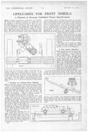
A New Shock Absorber.
THE specification of E. B. Bronghton, W. Emmett and D. T. Brock, No. 280,451, describes a device • which it calls a shock absorber. We are not at all sure what a shock absorber really is, as we see the term applied to devices which make the action of the springs more lively and, on the other band, to friction-producing devices which make springs more sluggish. In the present case the device is one of the latter type, as its object is to bind the leaves of a spring together whilst the spring retains its camber, but to release the pressure as the spring flattens.
It will be seen that thereare two points of bearing on the concave side of the spring,. whilst on the convex side there is only one, therefore, the more the spring flattens, the less the damping effect exerted by the device which we should
therefore call a snubber. The specification points out that this arrangement will allow the spring to flatten, as when passing over a bump, but will retard their return to their original camber. Thedevice can be fitted to any existing spring.