


THE DIESEL ENGINE AND ITS DESIGN.
Page 47
Page 48
Page 49
If you've noticed an error in this article please click here to report it so we can fix it.
Continuation of an Article which Analyses Diesel Engine Design and Indicates the Difficulties which have had to be Overcome in Fuel Injection.
IN our previous issue we outlined the original conception in 1892 by Dr. Rudolph Diesel, of the engine that bears his name, showing that he met with a measure of success for the reason that he had, accidentally perhaps, provided means for injecting the fuel;
We also pointed out that, on the other hand, Mr. Ackroyd Stuart, who actually anticipated Diesel in the essential conception, failed in his endeavours because he was not able to deliver the fuel to the air that he had compressed in the combustion chamber in the manner which he had specified—that is, "in a fine spray at the end of the compression stroke."
The situation was saved for Diesel, as he had already provided compressed air for the injection of coal dust.
kekroyd Stuart, on the other hand, entirely relinquished his fundamental principle and adopted a device which eliminated the necessity for anything beyond a very primitive form of injection, and whilst, in our previous issue, we recalled some of the efforts that have been made to reach the goal in a direct manner, but without the use of compressed air as an injecting and pulverizing medium, in this issue we propose to deal with some of the efforts that have been made to build up a Diesel engine from the same fundamentals and from the same plan as was employed by Stuart and developed by Hirsch, Brons, Ellwe and others, the first-named being a very obvious transition.
We terminated the previous article by pointing out two methods of fuel supply, the differential valve and pump and the pre-ignition chamber. It was anticipated that each would in itself suffice and that they were, therefore, alternatives, but practice has shown that their concerted efforts were needed, for the pre-ignition chamber failed without the help of the differential valve, just as it was soon realized that the plunger of a pump would take a considerable angular period to accelerate to a speed that would produce the required pressure. In an engine turning at 300 revolutions this angular
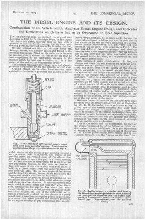
period would, perhaps, be as much as 20 degrees, the s pump being allowed to deliver into a valve chest located just above the jet and the valve consisting of a springloaded plunger terminating in a pin valve that was seated in the jet duct. This is shown in Fig. 1. The fuel was delivered below the plunger, and when the pressure rose to the required amount (varying between 500 lb. and 1,500 lb.) the valve was raised and the fuel passed to the jet ; then, as the pressure fell, the valve again seated Itself.
This introduced many complications. At first, the plunger was made free and acted as an hydraulic accumulator and the pressure would have remained Constant had it not been for the inertia at the plunger, which, as speeds were increased, played havoc with the system until the design was modified and the movement of the plunger was arrested by a stop. This, obviously, resulted in a considerable variation of pressure, but here, again, we have a tailing off of the pressure as the valve closes, and an actual extruding of a small particle of oil as the valve found its seat.
This is the system that is generally used for the conventional two-stroke engine, the horizontal highcompression oil engine and so on, but an analysis of output, of b.rn.e.p., and of fuel consumption, to say nothing of the exhaust, gives a very definite answer as to the real value of the system.
We have further information on this point from some research that has lately been carried out at Cambridge by Mr. D. H. Alexander, and a reference to Fig. 6, giving one of the curves obtained, will show that, although the plunger is operated with a sharp cam which is designed to the utmost mechanical limits, the movement is quite harmonic and obviously inadequate, whilst the pressure line and the opening and closing periods of the valve hardly need comment, although they do require some explanation,
This is the secret and the explanation not only of the graph reproduced but of the failure to realize that this system is quite inadequate. It is the explanation of Stuart's failure, it is the explanation of the success of the Vickers pressure-fuel valve system and, to use common parlance, it is the "nigger on the face" that has caused all the trouble and has allowed blast air to gain such a definite hold.
Oil is compressible to a very considerable degree (1 per cent. at 3,000 lb.), and, being compressible, it will transmit waves that travel at high speeds and are very violent. Let it be assumed that the pipe-line is normal In length and that the pump and valve clearances are as small as possible, and it will be found that there can be no less than 20 per cent, of the delivery stroke of the pump absorbed in compression.
Certainly, it would appear that this compressed fluid could be stored in the space between the delivery valve of the pump and the differential valve at the jet, and In one large engine at least, where there is over 25 ft. of pipe between the pump and the jet, this pipe actually acts as a reservoir for the compressed oil, each succeeding delivery raising the pressure sufficiently to lift the differential valve. This, again, introduces a danger, for the valve is just floating and there is no pressure forcing it on its seat, so the slightest amount of grit will prop it open and produce dribble during the whole of the cycle. Something of this kind, no doubt, happens in the smaller higher-speed engines, but if we come to the speeds such as have been mentioned, the actuation of this plunger cannot follow proportionately—that is obvious—and we would soon arrive at quite an impossible position where the movement of the valve was governed by waves in the fuel, as are so graphically shown in Fig. 6.
The system has lamentably failed in slow-speed heavy engines, and, obviously, cannot be considered for speeds above 500 r.p.m., whilst in the case of direct pumping without the intervention of the differential valve, when the pump delivery valve closes, there is, perhaps, 20 per cent. of the charge under compression between the pump and the jet, an appreciable portion of which will pass into the cylinder in the form of dribble.
These disabilities have been recognized in some instances; the Blackstone engine has a measuring pump that delivers fuel in front of a free plunger having a spring with an initial load. At the top of the stroke a rocker strikes this plunger and compresses the spring from its stop and subjects the fuel to pressure; finally, a trip valve, also operated by the rocker, admits the fuel into the engine. This has many advantages, but it is limited to slow speeds and low pressures, yet it is a welcome indication that there is some recognition of the faults of the conventional system.
The other line of investigation is a very subtle one. It started about the year 1898 in America with the a30 Hirsch Low engine (No. '1,118 of 1899) and the in ventors roughly pumped some oil into a small hot capsule, w Ii e r part of it exploded and blew the remainder into the cylinder proper. This system operated the first internal combustion engine to cross the Atlantic, and that is something to its credit. It I next appeared in ( the guise of the Brons engine (No.
14,165 of 1904), but in this case it was untimed and • a very fine adjustment of holes, etc., had to be accomplished to enable it to function.
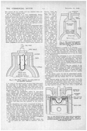
The next step was obviously the timing of the injection into the capsule, and this was the Ellwe, shown in Fig. 3, which was immediately followed by many variants, the principles remaining more or less the same as the Hirsch-Low.
Its one outstanding advantage is that the conditions that have been set out earlier in this article relative to fuel pumping need only be approximated. The final pulverization and injection being produced by the preignition in the capsule, it is a zig-zag mule track over the mountain compared with the railway tunnel through it, and it operates as follows:— . The hole, or holes, leading from the capsule to the combustion chamber, must have some determined and definite area. The capsule, or part of it, should be insulated from the cooling medium. A timed and regulated spray of fuel must be injected into the capsule as required.
As the piston nears the end of compression stroke, although there will be a rise of pressure in the capsule, this pressure will lag behind that of the combustion chamber.
The injected spray of fuel will, therefore, meet the Incoming air and will Mix with it, and, after a certain interval and at somewhere about top centre, there will be ignition inside the capsule and a small proportion of the fuel will be burned. This will cause a rapid rise
of pressure in the capsule to above the combustion chamber pressure anti a consequent flow from the former to the latter, this flow consisting of oil, oil vapour, burning oil and products of combustion. This injection of the fuel into the combustion chamber air produces ignition and a rise in the combustion chamber pressure; therefore the flow of fuel is more or less automatically regulated.
It has the advantage of adjusting itself to the en gine revolutions, as, with the higher speeds and lesser time intervals, the constriction between the capsule and the combustion chamber produces a greater pressure difference and, therefore, more rapid flow, both inwards to complete internal pulverization and outwards into the combustion chamber.
This is claimed as its saving clause, but the real reason for its existence is that which brought into being the Ffornshy-Aekroyd bottle neck and combustion chamber—the failure to pump the oil properly. There Is a strange similitude between the two. In each case we have the rough spraying of the fuel (in many case§ by means of the differential valve) into a chamber filled with inert gas, then we have the rise in pressure in the cylinder forcing the air into this chamber through a comparatively small orifice; next we have the ignition of the fuel and air in the chamber, and then the flow of fuel and burned gases into the air remaining in the cylinder and the final combustion in the cylinder
proper. This is identical—the differentiation is a matter of degree and proportion. The causes are the same, but the proportions of capacities and pressures have produced the improvement in performance.
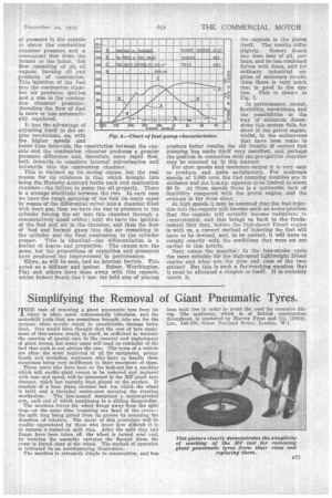
Ellwe, as will be seen, had an internal ferrule. This acted as a diffuser and Igniter. Sulzer, Worthington, Fiat and others have done away with this capsule, whilst Robert Bosch has tken the bold step of placing
the capsule in the piston itself. The results differ slightly. Robert Bosch has done best of all, perhaps, and he has combined forces with Benz, and for ordinary industrial engines of moderate revolutions there is very much that is good in the system. This is shown in Fig. 5.
In performance, output, flexibility, revolutions, and the possibilities in the way of minimum dimensions this system falls far short of the petrol engine, whilst, in the endeavours that have been made to produce better results, the old trouble of correct fuel pumping has made itself very manifest, and perhaps the position In connection with the pre-ignition chamber may be summed up in this manner.
For slow speeds and moderate output it is very easy to produce, and quite satisfactory. For moderate speeds of 1,000 revs, the fuel pumping troubles are in evidence and she b.m.e.p. appears to be limited to about 90 lb. At these speeds there is a noticeable lack of flexibility compared with the petrol engine, and the exhaust is far from clear.
At high speeds it may be assumed that the fuel injection into the capsule will become such an acute problem that the cap.sule will actually become redundant to requirements, and this brings us back to the fundamental fact that, before the high-speed Diesel engine is with us, a correct method of injecting the fuel will have to be devised, and, to be correct, it will have to comply exactly with the conditions that were set out earlier in this article.
Next comes the question: Is the four-stroke cycle the more suitable for the high-speed lightweight Diesel engine and what are the pros and cons of the twostroke? But this is such a far-reaching question that it must be allocated a chapter to itself. It is certainly worth it.