


PATENTS SUMMARIZED.
Page 24
If you've noticed an error in this article please click here to report it so we can fix it.
Sparking Plug Improvement.
The name of K. E L. Guinness is well known amongst. the field of 'inventors whose energies are to a, large extent concentrated upon the improvementof present-day sparking plug construction with a view to 'securing in creased efficiency of this all-important ignition accessory. •
. This present invention, patent specification IVO. 111,256, relates to plugs of the kind having a 'removable centre electrode which slides in a tube engaged at its inner and with the insulation of the-phig, and -threadedat its outer end to receive the •electrode ora member engagedwith it. Its „ilia% purpose is .to introduce this .feature of removability into plugs constructed of built-np layers of mica, the removal of the electrode leaving the mica firm and unloosened. This is effected by forming a flange on the inner end of the metal lining tube through which the electrode passes, and by building this flange in and compressMg it with' the,, discs which form the body of the insulation. This tube being in good conductive contact with the electrode•may carry at its outer end radiating fins for dispersing the heat. To en-sure gas .tightness the threaded portion of the plug which screws into this tube may compsess between it and the end of the tube a suitable packing ring.
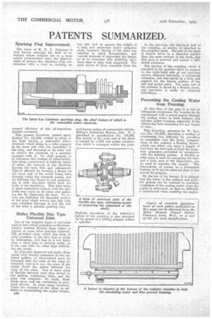
Halley Flexible Disc Type Universal Joint.
One of the simplest types of universal joint is that which' embodies as the transmissive medium flexible discs either of leather or some other suitable 'material. pr!ncipal claim which this form of joint possesses is, the fact that it needs nä lubrication, and that it is not liable after a short time to develop rattle, as is the case with the older type embody ing pin joints... •
As originally designed and made, these joints were usually composed of two oppased spiders' or three-armed jaws, so arranged that the ends' of the arms alternated; that in to say, the arms of one spider faced the Spaces between the arms of the other. One or More discs of flexible material were then bolted to the spiders, connecting them, and the joint was complete. So made, these joints gave, and ase continuing to give, good service. In some cases, however, where the material of the' discs, in addition to transmitting the engine torque,
060
has also had to sustain the weight of a long and somewhat heavy propeller shaft, excessive flexing of the discs has resulted in rapid deterioration, and various methods of improving the design so as to overcome this disability have from time to time been suggested. The most recent of these emanates from the well-known maker of commercial Vehicles, Halley's Industrial Motors, Ltd. It is described in specification No. 110,680. The weieht of the joint and of the shaft is -carried by a bah and socket construction which is arranged within the joint.
Endwise movement of the individual halves of the coupling is also provided for by means of a sliding plunger Within a cylinder. In the drawing, the left-hand half of the coupling, as shown, is attached to the propeller shaft. The end of the shaft • is turned down to a diameter smaller than the main portion of the shaft, and this parts.is screwed and carries a ball. ended extension.
The portion of the coupling which is attached to the gearbox shaft (it appears on the right-hand side of our drawing) carries, disposed internally, a cylindrical extension, and this serves as a slide and• support for the female portion of the ball and socket joint. The outer end of the cylinder is clos.ed by a flexible Cover, and provision is made for adequate lubrication.
Preventing the Cooling Water from Freezing.
At this time, of the year it is not an infrequent,. occurrence for trouble .to be experienced with a petrol engine through the cooling water in both radiator and cylinder jacket freezing, especially if the vehicle has been' stationary for any length of time.
This invention patented by W. Benson (No. 111,209cs describes a Method of overcoming this difficulty by providing in conneeticin with the -lower comport-. ment of the radiator a 'heating binmer, which can either rely upon a supply of fuel from the fuel tank or from the acetylene generator embodied in connection With the lighting system. A flexible or other pipe is used for conveying the fue7, and a cock, seep in the illustration, can be used to regulate the supply. The burnerf can, of course, be a permanent feature, or it can be removed after it has
served its purpose.. ,
By the use of the burner, it is claimed , that the water in the radiator, and cylinder jackets can be warmed to maintaia eirculation of the coolingswater.w hen theengine is stationary, so that no.diffieulty • is experienced when cranking the engine.