


New Scheme for Refuse Collection
Page 54
If you've noticed an error in this article please click here to report it so we can fix it.
PATENT No. 601,569, which comes from She!yoke and Drewry, Ltd., and C. Edwards, both of Letchworth, Herts, shows a new system for refuse
collection. The outfit consists of a " mother" vehicle, which is filled with the loads collected by a number of small hand-trucks.
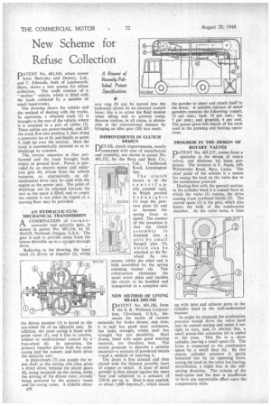
The drawing shows the vehicle and the method of dealing with the trucks. In operation, a wheeled truck (1) is brought to the rear of the vehicle, where it is attached to a pair of cables (2). These cables are power-hauled, and lift the truck first into position 3, then along a conveyor (as at 4), and finally to point 5, high up over the interior. Here the truck is automatically inverted so as to discharge its contents.
The reverse sequence is then performed and the truck brought back empty to ground level. Power is provided by an electric motor and reduction gear (6), driven from the vehicle batteries, or. alternatively, an allmechanical drive may be used with the engine as the power unit. The point of discharge can be adjusted towards the rear as the space is filled, and to empty the vehicle it can either be tipped or a moving floor may be provided.
AN HYDRAULIC-CUMMECHANICAL TRANSMISSION ACOMBINATION of torqueconverter and epicyclic gear, is shown in patent No. 601,116, by D. McGill, Portland. Oregon, U.S.A. The gear is said to provide ratios from the lowest desirable up to a straight-through drive.
Referring to the drawing, the input shaft (1) drives an impeller (2), whilst
the driven member (3) is keyed to the sun-wheel (4) of an erSicyclic unit. In addition, the outer casing is fitted with guide vanes (5), and is free to revolve, subject to unidirectional control by a free-wheel (6). In operation, the primary impeller drives both the outer easing and the runner, and both drive the epicyclic unit.
A plate-clutch (7) can couple the input shaft to the casing; this then gives a direct drive, because the planet gears (8), being mounted on the casing, assist the driving of the driven rotor, already being powered by the primary vanes and the casing vanes. A slidable obtur
a34
ator ring (9) can be moved into the hydraulic circuit by an external control lever; this is to arrest the fluid motion when idling and so prevent creep. Reverse motion, in all ratios, is obtainable in the conventional manner by bringing an idler gear (10) into mesh.
IMPROVEMENTS IN CLUTCH DESIGN
DETAIL clutch improvements, mostly L./concerned with ease of manufacture and assembly, are shown in patent No. 601,332, by the Borg and Beck Co., Ltd., Tachbrook Road, Leamington Spa.
The clutch shown is of the centrifugally assisted type, in ivhich pivoted bobweights (1) load the pressure plate (2) and so increase the spring force at speed. The essence of the invention is that the clutch
assembly is fastened into a unit by small flanged pins (3). which can be attached to the flywheel by two screws, whilst the other end is held assembled by the spring retaining washer (4). This construction eliminates the usual cover plate and enables the clutch to be handled and transported as a complete unit.
NEW METHOD OF LINING BRAKE DRUMS
PATENT No. 601,186, from the S. K. Wellman Corporation, Cleveland, U.S.A., dis
cusses the merits of various materials for brake drums; cast iron, it is -said has good wear resistance, but lacks strength, whilst steel has strength but not durability. Steel drums, lined with some good wearing material, are therefore best. The patent proceeds to describe a suitable material—a mixture of powdered metals —and a method of inserting it.
The drum is first cleaned and then plated with the thinnest possible layer of copper or nickel. A layer of metal • powder is then placed against the inner face and subjected to a pressure of 250 lb. per sq. in. Heat is next applied, at about 1,600 degrees.F., which causes the powder to sinter and attach itself to the drum. A suitable mixture of metal powders contains the following: copper, 73 per cent.; lead, 14 per cent.; tin, 7 per cent.; and graphite, 6 per cent. The patent gives full details of the tools used in the pressing and heating operations.
PROGRESS IN THE DESIGN OF ROTARY VALVES
DATENT No. 601,217, comes from a
specialist in the design of rotary valves, and discloses his latest proposals. The inventor is F. Aspin, 149, Walmersley Road, Bury, Lancs. The chief point of the scheme is a means for easing the load on the valve due to the combustion pressure.
Dealing first with the general outline; in the cylinder head is a conical bore in which the valve (1) rotates, the drive coming from overhead bevels (2). The curved space (3) is the port, which also forms the bulk of the combustion chamber. As the valve turns, it lines up with inlet and exhaust ports in the cylinder head in the well-understood manner.
As might be expected, the combustion pressure would drive the valve hard into its conical seating and make it too tight to turn, and, to obviate this, a small piston-like extension (4) is added to the cone. This fits in a short cylinder, leaving a small space (5). The latter is connected to the combustion space by a small duct (6). By this means, cylinder pressure is partly balanced out by an opposing force, easing the load on the valve but leaving, nevertheless, a slight bias in the selfsealing direction. The volume of the .back-space and the duct is insufficient to have any appreciable effect upon the compression ratio.