


Variable Superimposition of Trailer Weight
Page 56
If you've noticed an error in this article please click here to report it so we can fix it.
PAT-ENT No. 468,740, by K. and H.
Schreiter, 122, Gothaerstrasse, Wechmar, Germany, shows a scheme by which a normal two-axle trailer can be moved .forward so as to transfer a portion of its weight to the tractor, without, however, lifting its front wheels from the ground.
The drawbar (1) is attached to the tractor at one end and the trailer front axle at the other. The trailer body rests upon a strut (3) which has its lower end ball-jointed into a slidable housing (4). A kicking device (2), when opened by the. -driver," allows the tractor to be driven backwards, taking the wheels (5) with it, into the position shown by dotted lines.
To' prevent. the trailer from moving during this shortening operation, the strut (3) is allowed a slight rocking movement, which causes it to apply the -trailer brakes while the tractor is moving into position.
Steadying Oil-engine Idling Speed.
AN oil engine, in which the fuel quantity is governor controlled in proportion to the intake suction, may often fail to run evenly when idling, owing to the individual impulses of the pistons making themselves perceptiblein the governing system. A scheme for averaging-out these impulses is revealed in patent No. 468,615 by Robert Bosch , A.G., of Stuttgart, G e r many.
The drawing shows an air intake, with a manually controlled throttle valve (3) and. a connection (1) to the cylinder operating the rack of the injection pump. The improvement consists of a: by-pass to the throttle valve, in which is a small spring-returned flap valve (2). This, by reason of its lightness, is able to move and pass air during violent fluctuations of pressure.
Ingenious End-tipping Mechanism.
PI A DESIGN of hand-operated tipping —mechanism is shown in patent No. 468;656 • by G. Murdoch, 31, Queen's Road, Monkseaton, North/AB..
umberland. The apparatus compnses a pinion (3) on the handle-shaft, meshing with a gear on a second shaft. The last-named carries another pihion (4) which engages with a toothed sector (5) pivoted on a radius arm (2), a roller (1) working under a plate forming the connection with the frame. The apparatus is illustrated in the fully tipped position. When lowered,, the arm (2) moves to a horizontal position between two plates which prevent rattle.
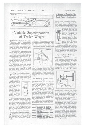
Fuel Metering by Control of Injector Needles.
ELIMINATION from an oil-engine injection system of the orthodox pump is the subject of patent No. 468,360, from G. Amery, 3, Greville Road, London, N.W.6. The basic principle of the scheme is the use of a high-pressure unmetered fuel supply to the injectors, the quantity being controlled by positive opening and closing of the needle valves, an operation which is performed hydraulically. In the application a single pump creates the required pressure for both functions.
The apparatus comprises a high-pressure continuously working fuel pump, an hydraulic piston attached to each injector needle, and a timer-distributor. The drawing shows an iniector, to the lower. end of which is led the continuous high-pressure fuel supply (3). This tends to lift the needle against the spring, but is opposed by a greater force on the piston (4), which is'also.fed from the fuel supply via pipe 1. Inject:On is brought about by a pressure release in the upper chamber, which is Controlled by a rotary timing and distributing valve. Pipe 2 serves to 'collect 468;360 leakage and return it to the supply.
The patent describes also the construction of the distributor, and, in the provisional specification, mentions the application of the system to the operation of exhaust and inlet valves, thus abolishing the need for a camshaft.
Registering Engine Work Output by Aneroid.
"THERE has, of late, been some doubt 1 as to whether mileage alone is asufficent basis for calculating the service that should be afforded by a vehicle engine. An instrument which indicates the power output at.any moment, also integrating it to a sum over a long period, is shown in patein No. 468,663, by E. Mier, 60, Wotan
strasse, Munich, Germany. The scheme is based on the assumption that the power output at any instant is proportional to the intake pressure, and this is directly indicated by a pointer (6) connected to an aneroid (1). housed in a casing piped to the intake.
The integrator comprises a counting mechanism (not shown) which records the oscillations of a spindle (4). This is moved primarily by an engine-driven crank (5), but is subject to modulation by the aneroid, which raises or lowers a sliding link (3) and thus varies the ratio between the crank and the recorder according to the power being developed. ' To allow for variations in the temperature of the in-going gases, a bimetallic couple (2) is placed in their path, and by its bending makes a further adjustment to the position of the sliding link (3).