A Power Take-off
Page 74

If you've noticed an error in this article please click here to report it so we can fix it.
for the New Ford
A Rdsumd of Recently Published Patent Specifications.
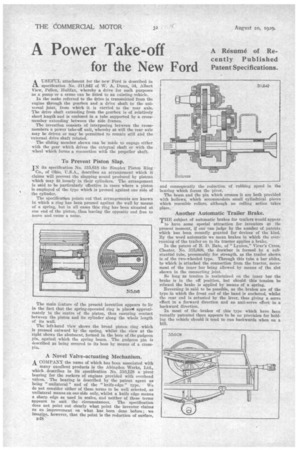
A -USEFUL attachment for the new Ford is described in L-1. specification No. 311,842 of W. A. Dunn, 34, Albert View, PeHon, Halifax, whereby a drive for such purposes as a pump or a crane can be fitted to an existing vehicle.
In the make referred to the drive is transmitted from the engine through the gearbox and a drive shaft to the universal joint, from which it is carried to the rear axle. The drive shaft extending from the gearbox is of relatively short length and is enclosed in a tube supported by a crossmember extending between the side frames.
The invention consists of interposing between the crossmembers a power take-off unit, whereby at will the rear axle may be driven or may be permitted to remain still and the external drive shaft rotated.
The sliding member shown can be made to engage either with the gear which drives the external shaft or with the wheel which forms a connection wit 6 the propeller shaft.
To Prevent Piston Slap.
IN its specification No. 315,618 the Simplex Piston Ring
Co., of Ohio, U.S.A., describes an arrangement which it claims will prevent the slapping sound produced by pistons which may fit loosely in their cylinders. The arrangement is said to be particularly effective in eases where a piston is employed of the type which is pressed against one side of the cylinder.
The specification points out that arrangements are known in which a ring has been pressed against the wall by means of a spring, but in all cases this ring has been situated at one end of the piston, thus leaving the opposite end free to move and cause a noise.
The main feature of the present invention appears to lk in the fact that the spring-operated ring is placts1 approximately in the centre of the piston, thus ensuring contact between the piston and its cylinder along. the whole length of its wall.
The left-hand view shows the broad piston ring which is pressed outward by the spring, whilst the view at the right shows the abutment, formed in the bore of the gudgeon pin, against which the spring bears. The gudgeon pin is described as being secured to its boss by means of a crosspin.
A Novel Valve-actuating Mechanism. A COMPANY the name of which has been associated with many excellent products is the Abingdon Works, Ltd., which describes in its specification No. 310,128 a pivot bearing for the rockers of engines provided with overhead valves. The bearing is described by the patent agent as being " unilateral " and of the "knife-edge" type. We do not consider either of these terms to be well selected, as unilateral means on one side only, whilst a knife edge means a sharp edge as used in scales, and neither of these terms appears to suit the circumstances. The specification does not point out clearly what point the inventor claims as an improvement on what has been done before; we imagine, however, that the point is the reduction of surface, B48
and consequently the reduction bearing which forms the pivot. of rubbing speed in the The beam and the pin which crosses it are both provided with hollows, which accommodate small cylindrical pieces which resemble rollers, although no rolling action takes place.
Another Automatic Trailer Brake.
THE subject of automatic brakes for trailers would appear
to have some special attraction for inventors at the present moment, if one can judge by the number of patents which has been recently granted for devices of the kind. By the word automatic we mean brakes in which the overrunning of the trailer on to its tractor applies a brake.
In the patent of B. D. Bate, of " Lynton," Vicar's Cross, Chester, No. 315,608, the drawbar is formed by a substantial tube, presumably for strength, as the trailer shown is of the two-wheeled type. Through this tube a bar slides, to which is attached the connection from the tractor, movement of the inner bar being allowed by means of the slot shown in the connecting joint.
So long as tension is maintained on the inner bar the brake is in the off position, but should this tension be relaxed the brake is applied by means of a spring.
Reversing is said to be possible, as the brakes are of the type in which the front end of the band is anchored, whilst the rear end is actuated by the lever, thus giving a servo effect in ft forward direction and an anti-servo effect in a backward direction.
In most of the -brakes of this type which have been recently patented there appears to be no provision for holding tho vehicle should it tend to run backwards when on a bill.


