


A NEW S.M.C. FOUR-WHEELER
Page 58
Page 59
Page 60
Page 61
If you've noticed an error in this article please click here to report it so we can fix it.
For Passenger Service
TN the issue of The Commercial Motor dated
December 18th, 1928, we made . the exclusive announcement that the Sunbeam Motor Car Co., Ltd., was 'about to produce new six and four-wheeled bus chassis. A description of the sit-wheeler followed and preliminary details were given of the four-wheeled chassis. We are now able to give full particulars, with illustrations, of the latter chassis, the first model of which has just .been completed by a special department of the company's works at Wolverhampton, dealing with the commercial-vehicle side of the business.
• Before actually describing the new chassis it might • here be opportune to state that one of six-wheeled models has been fitted with a large passenger-carrying double-dect: • body and has for some time been on ' town service. We are assured . that the results have been remarkably good. It is clear, therefore, that the Sunbeam Co. has jumped right into the front rank as a commercial' chassis manufacturer, an equivalent Position to that which it has held for many years in the Private-car field.
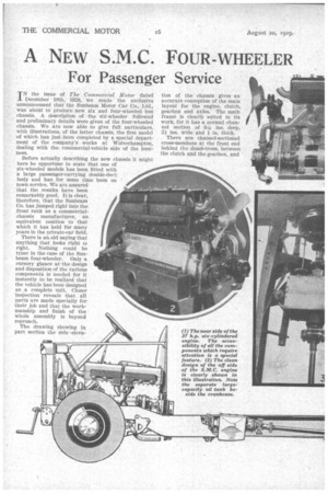
There is an old saying that anything that looks right is right. Nothing could be quer in the case of the Sunbeam four-wheeler. Only a cursory glance at the design and disposition of the various components is needed for it instantly to be realized that the vehicle has been designed as a complete unit. Closer Inspection" revealS. that, all parts are made specially for their job and that the workmanship and finish of the whole assembly is beyond reproach.
The drawing showing in part section the side .eleva
at the propeller-shaft centre bearing. Another channel-sectioned member runs fore and aft between the two last-named cross-members, on the right-hand or off side of the transmission line and so gives additional bracing in the heavily loaded section amidships. In addition, two substantial tubular cross-members, 3 ins. in diameter, with large end flanges, run respectively between the rear-spring front-end brackets and close to the rear-spring rear-end shackle brackets. The chassis is suspended on semi-elliptic springs at the front and rear.
Before proceeding farther we will give a few general dimensions, in order to familiarize readers with the size and passenger-carrying capabilities of the vehicle. Intended primarily as a chassis to carry 32-seater single-deck bus bodies, or, alternatively, 26-seater luxury-coach bodywork, the frame is built up to the maximum dimensions permitted by the Ministry of
Transport regulations. The wheelbase and track dimensions of 16 ft. 6 \ins., and 6 ft. 5-i. ins, front and 6 ft. 11 rear, respectively, provide . a turning circle Of 54 ft. 6 ins.—a moderate figure for the size of the vehicle.
Although the overhang at the mugs under 7 ft. 6 ins., the body .,pace measured from the rear face of the dashboard is as large as 20 ft. 6 ins.—this despite the fact that a six-cylindered engine is used fm. propulsion. The overall length, exclusive of the starting handle, is 26 ft. The loading height is 2 ft. 1 in. with 38-in. by 7-in. tyres, or 2 ft. 01 in. with the alternative equipment of 36-in by 6-in. tyres. Except under the rear axle there is a ground clearance of 10i ins.
We can now turn -our, attention to a consideration of the power unit, the transmission, etc. Although the design of the engine is similar to that of the six-wheeled chassis (already described), it is thought that a comprehensive edescription of the new model will not be out of place, because there are many features of outstanding interest in the layout.
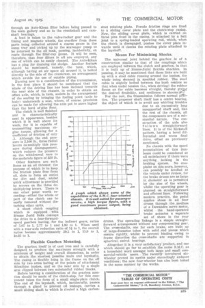
As might be expected, the new engine is not quite so large as that of the six-wheeler, for the simple reason that its duties are not so heavy. Nevertheless, it is amply powerful for its work, as the following particulars will testify :--The actual dimensions of the cylinders are, bore 100 mm., stroke 140 mum., capacity 6,597 c.c., and the R.A.C. rating is 37.2 11.p. Reference to the power-curve will show instantly that the characteristics of the unit are ideally suited for bus or coach operation, because a high torque figure is obtained, in conjunction with a good maximum-power output. .The overall gearing, engine to road wheels, is such that 1,000 engine
-------'-')...... r.p.m. corresponds to a road speed 'of 20 m.p.h. Being a new product, it is not surprising that the unit is planned on ultra-modern lines. Thus, the combustion chambers are hemispherical and have inclined overhead valves for the inlet and exhaust systems. Unlike the average engine with inclined valves, however, the camshaft is contained in the crankcase—an arrangement which makes for quiet miming and assists materially in connection, with maintenance work.
Facilitating umeep.
The main components of the engine, such as the cylinder block, cylinder heads, crankcase, etc., are, as might be expected, of a substantial nature, although not unduly heavy. There is one item of more than passing interest, that is, the cylinder heads are in two castings—an arrangement which, amongst other
things, is commendatory owing to the facility with which decarbonizing can be effected. Indeed, if the available time for the operation be limited, only three cylinders need be treated at a time.
In the interests of smooth running the crankcase is well ribbed internally and each of the seven bearings of the crankshaft is very well supported. Machined all over and accurately balanced, this component (the crankshaft) is sturdy-looking. It has continuous oilways throughout its length and ample provision is made for taking end thrust by the use of hardened thrust washers, which are fitted to No. 1 bearing. The pistons are of the Zephyr type, having aluminium heads and steel trunks.
Valve Operation
As we have already indicated, the valve operation is of outstanding interest. The camshaft, contained in the crankcase and rotated by spiral-tooth gears from the end of the crankshaft, communicates with the valves by means of push rods, the six inlets being opened by rods running across the engine, between the cylinder bores, whilst the exhaust-valve push rods run practically parallel to the cylinders. The valves themselves, together with the rockers, springs, etc., are enclosed by oiltight covers fitted in pairs to each of the two cylinder heads.
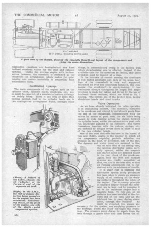
One of the most desirable features in the layout of this new S.M.C. engine is the manner in which all the components requiring periodic attention are grouped on the near, or accessible, side of the unit The dynamo and water pump are mounted in line, one on each side of the timing case, the ignition distributor points
vertically upward, whilst the magneto and starter motor are disposed neatly in the rear cheek of the crankcase. 'Again, both the inlet and exhaust systems are readily accessible, as .they, too, are on the near side, so that all running adjustments can be carried out with the minimum of trouble.
It is clear that in planning the lubrication system every precaution has been taken to ensure an adequate supply of oil reaching all the working surfaces throughout the whole of the engine. The dry-sump principle is employed largely because the lubricant can be kept cool by pumping it out of the crankcase proper into a separate tank. To this end, an oil radiator has been installed at the forward end of the tank and all the lubricant has to pass, during circu lation, through this radiator. As might be expected, two pumps ape -necessary for the system, one supplying pressure to the bearings, whilst the other scavenges the crankcase. The pressure pump draws its supply from the tank through a gauze filter and then forces the oil through an Auto-Klean filter before being passed to the main gallery and so to the crankshaft and camshaft bearings.
A lead is taken to the valve-rocker gear and the timing and magneto wheels, the overflow from these parts being collected around a coarse gauze in the sump tray and picked up by the scavenger pump to be returned to the oil tank,. passing, incidentally, en route through the• filler-cap gauze. It will be seen, therefore, that four filters in all are employed, any one of which can be easily cleaned. The Auto-Klean has a plug for draining out sludge. Another feature should be mentioned, namely, the tank, which, although having an air space all around it, is bolted directly to the side of the crankcase, an arrangement which avoids the use of outside piping.
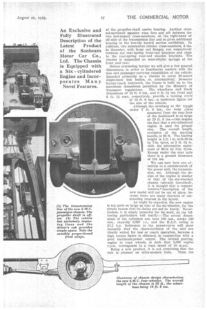
urning now to a consideration of the transmission, in the first place it should be mentioned that the whole of the driving line has been inclined towards the near side of the chassis, in order to obtain an offset axle, which, in turn, assists in the arrangement of the seating by bringing the fouling point (axle to body) underneath a seat, where, of course, provision can be made for allowing the axle pot to move higher than the level of )ithe floor.
The clutch is well finished and is characteristically neat in appearance, besides which it is well above its work, for it is capable of transmitting maximum engine torque, allowing for a coefficient of friction of only .1. Although the end pressure is 2 100 lb. three radial levers de-multiply this pressure during disengagement, which reduces the pressure on the withdrawal race to the moderate figure of 350 lb.
Other features are such items as an oil thrower, the purpose of which is to keen the friction plate free from oil, slots to form an outlet for dirt and dust, whilst quick adjustment is provided by screws on the three demultiplying levers. There is one other point worth recording—either the whole or part of the clutch can he easily removed without disturbing other units.
• A short clutch coupling which is equipped with Simms Jurid links conveys the drive to a four-forwardspeed gearbox having, for the indirect gears, ratios of 5.07 to 1, 2.77 to 1 and 1.80 to 1. When used with a rear-axle reduction ratio of 51 to 1, the overall ratios become approximately 29.2 to 1, 15.9 to 1, 10.35 to 1. 1111111
Zo
0
':
:
20
Illy
DI
liolir III Flexible Gearbox Monnting, The gearbox itself is of cast iron and is carefully designed, to produce the maximum strength with a minimum of weight and overall dimensions, in order to obtain the shortest possible main and layshafts. The casing is flexibly hung in the frame on the off side by two arms having at the points of attachment Silentbloc bushes, and on the neer side by a single arm clipped between two substantial rubber blocks.
Before leaving a consideration of the gearbox mention should he made of the clutch-stop, for this component takes the form of a small single-plate clutch. The end of the layshaft, which, incidentally, passes through a gland to prevent oil leakage, carries a small sliding shaft to which is riveted a high carbon steel rotating plate. Ferodo friction rings are fixed to a sliding cover plate and the clutch-stop casing. Now, the sliding cover plate, which is carried on three pins fixed in the casing, is attached by a ball joint to a spring-loaded operating rod, which, when the clutch is disengaged, pushes the cover plate inwards until it checks the rotating plate attached to the layshaft.
Means For Minimizing Shocks.
The universal joint behind the gearbox is of a construction similar to that of the couplings which are employed Ketween the clutch and gearbox, in that it is built ug of Simms-Jurid flexible shackles. in passing, it may be mentioned that these links are built up with a steel cable running around the bushes, the whole being eh-leased in moulded rubber. The steel cable is slightly bowed between the bush centres so that when under tension (i.e., when driving) the rubber flexes as the cable becomes straight, thereby giving the desired flexibility, and resilience to shocksee)47 For the rest, the transmission follows normal Ohtice. The propeller shaft itself has a centre bearing, the object of which is to avoid any whirling troubles due to an excessively long unsupported shaft and, like the rest of the chassis, all tile components are of a substantial nature. The construction of the axle also folio w s straightforward lines. It is of the Kirkstall pattern, having a bevel differential and worm final drive, offset as previously mentioned.
No chassis with the speed potentialities of this Sunbeam could be considered at all satisfactory if there were anything lacking in the braking system. No coinplaint on.this score, however, can possibly be levelled at the vehicle under review, for the brake drums are as large in, diameter as is permitted by the size of the wheels, whilst the: operating gear is planned or straightforward and efficient lines. Following modern practice, the pedal applies shoes in all four drums through the medium of a Dewandre servo motor, whilst the hand-operated brake actuates a separate set of shoes in the rear drums. The operating linkage is a simple straightforward arrangement without any compensating gear. The cross-shafts, one for each brake,are built up of large-diameter tubes with solid _end pieces which ensure rigidity, whilst to prevent binding owing to frame distortion the cross-shafts are supported in spherical swivel bearings.
Altogether it is a very satisfactory product, and one which should go far to _establish the name S.M.C. as househeld word amongst both large and small commercial-vehicle users. The recently introduced sixwheelç proved its merits under exceedingly arduous conditions; the new four-wheeler has also been tested in the same manner by the works.
1111
II ..
j
mill
111 11
,
'''''acys pea tam?' „too