


Patents Completed.
Page 18
If you've noticed an error in this article please click here to report it so we can fix it.
SPUR WHEEL S.—Can nin g.—No . 2,137, dated 4th February, 1908.—According to this invention the teeth of the spur wheels are cut away so that they vary in width, each successive tooth being car. rower than the one preceding it. By this arrangement the narrowest tooth is next to the widest tooth which latter extends some distance beyond the narrow tooth preceding it, on both sides. By this means the wheel that is to be brought into mesh can be readily engaged with the wide tooth by axial movement: continued axial movement then brings it fully into mesh with all of the teeth. The end portions of some of the teeth may be bevelled on the rear face to prevent locking when coming into engagement.
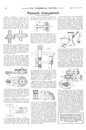
CHAIN CASE.—The Albion Motor Car Company and Another.—No. 18,072, dated 9th August, 1907.—According to this invention, a chain case is adapted to act as a radius rod. The case is formed of two sides (A, Al) having inturned flanges (As) and distance pieces (B). The sides are held together by means of a strip (C) of channel section. The case is attached
to the rear driving axle (El) by means of a disc (E) provided with a hub, which is lbosely mounted on the said axle, and it is connected to the differential shaft by means of a universal joint (G). A screw adjustment (F4) is provided for the alteration of the centres of the two shafts.
MOTOR VEHICLE. — Oaborn. — No. 17,317, dated 29th July, 1907.– -This invention relates to combined steering and driving wheels and is particularly applicable to three-wheeled vehicles. Motion is transmitted from the engine (13), through the sprocket wheel (19), chain (18) and sprocket wheel (20) to the sleeve (29). The yoke arms (32) in this sleeve, being pivotally connected with the ring (31), and the ring being pivotally connected to the hub (30), the wheel (20) is caused to ro tate. The wheel is firmly supported on the sleeve (29) through the medium of the web (40), collar (33), the wheel-supporting member (41), and ball bearings. But these members are mounted to oscillate about the vertical pivot (42) so that the wheel (16) may be readily displaced to steer the same, by the oscillation of the lever (43) which 's connected to the steering wheel (22) by the lever (26). In the form illustrated, the rigid supporting axle (27a), instead of passing through the hub of the wheel, is so mounted as to pass outside the circumference, but the mechanism is very similar, in most par. ticulars, to that described above.
RESILIENT WHEEL.—Rayner.—No. 3,267, dated 13th February, 1908.—The wheel is composed of two sets of cylinders (a) which radiate from the hub and are arranged side by side. Within the cylinders are plungers (c) having air chambers (cl) in which a quantity of air is trapped. The plungers (c) are provided with shoes (e), which engage in recesses (f1) formed in the rim (f). These recesses are made large enough to allow a slight circumferential movement of the rim relatively to the hub, and resilient blocks (g) are interposed between the shoes (e) and the walls of the recesses (f1). The cylinders (c) are partially filled with an elastic fluid and they communicate with one another by means of small ducts which are not shown in the illustration. Wooden-tread blocks (k) are provided and the rim (f) is composed of two rings, each of which engages a separate set of plungers, so that the rim may adapt itself to the contour or irregularities of the road. C ARBURETT ER.— J ules Grouvelle and Another.—No. 321,208 ; date under Convention, 14th February, 1907.—According to this invention a carburetter is provided with a device whereby the fuel may be shut off when required. The carburetting chamber (d) is provided with a gland (e) in which is a plunger (f). The plunger (f) is adapted to be advanced on to the spraying nozzle (c) and thereby to cut off the supply of fuel. This is effected by means of a lever (k), fulcrumed at (I), and one arm engages a head (h) which is carried by the plunger (f) and the other arm of the lever is connected by a rod (m) to a pedal situated at any convenient position on the dashboard. A snring (i) is interposed between the head (h) and the gland (e), so as to return the plunger (f) into the position shown, when not in use.
VARIABLE SPEED GEAR.—Dennis and Another.—No. 16419, dated 17th July, 1907.—According to this invention the cardan shaft is permitted to overrun the engine shaft, and thus to allow the vehicle to descend a hill by gravity. The engine
shaft (a) drives, through spur wheels (b., c, d), spur wheels (k, I, ni) on a countershaft (h), and the spur wheel (m) drives another spur wheel (n) on the cardan shaft (g). The spur wheel (n) is in the form of a ring, the outer periphery of which is provided with the usual spur teeth, and the inner periphery a series of recesses (i), which are adapted to engage the springpressed pawls (r) on the hub member (a). It will be seen that, with this arrangement, the shaft (g) and the hub member (o), which is keyed thereto, can overrun the outer ring (n). In order that the drive may be reversed, a clutch (u) is provided, which locks the outer ring with the hub member (a), and thus permits the drive to take place in the opposite direction.