


Rubber-cum-Torsion-bar Suspension System
Page 36
If you've noticed an error in this article please click here to report it so we can fix it.
A Résumé of Recently Published Patent Specifications
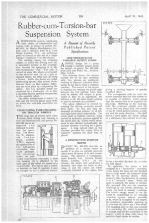
ASUSPENSION system, employing both rubber in compression and torsion rods, is shown in patent No. 567,492, by Works Development Co., Ltd., and J. Ehrlich, both of 2, York Street, London, W.1. An additional point of. interest is the use of a single tubular" backbone " for the chassis.
The drawing shows the complete chassis, in which the driving axle (1) is universally jointed to the transmission, because the springing is of the semi-independent type. The axle is carried by arms (2), which are attached to the movable unit (3) of a pair of opposed drams, the other one (4) being a fixture. Inside the drums are radial interlocking spokes, with rubber blocks between them, so that angular deflection can take place by compressing the rubber. The two movable drums are connected by a torsion-bar (5) so that a one-sided load is partially transmitted to the opposite wheel.
The front arrangement is similar; in this case the moving drums carry arms on which the stub-axle assemblies are built.
FACILITATING TYRE-CHANGING ON TRACTOR WHEELS
THE large size of tractor tyres often makes their fitting and removal a slow and laborious job, and patent No. 567,535 shows an improved r i m intended to facilitate the operation. The inventor. N. Lipman, 149, Camden Road, London, NW.!, suggests the application of the well-known detachable rim: w a,11 principle. The drawing shows the particular construction employed; a loose rim member (1) is attached to the main part of the wheel by means of a, ring of bolts. The hub is also a boltedon member, so that, if required, it may he changed to suit a different tractor.
NEW PRINCIPLE FOR VARIABLE OUTPUT PUMPS
A NOVEL design for a pump having a variable output forms the subject of patent No. 567,502,
from Jack and Heinz Inc., Bedford, Ohio, U.S.A.
The drawing shows the scheme worked out in its, bare essentials only two pistons are employed, working in adjacent cylinders which merge at the top to form a common chamber. The control of the output
is obtained by varying the phase angle between the two pistons; when these work in unison, full output is given, whilst if they be in opposition, the delivery is nil, the fluid simply passing to and fro between the cylinders.
The phase difference is created by rotating the driving eccentrics around their shaft. To this end they are mounted on helical pinions (I) of leftand right-hand pitch respectively. The whole shaft is slidable endwise, being moved by hydraulic pressure applied to the closed end (2), whilst return movement is also effected hydraulically, the annular chamber 3 serving for a piston space. A long splined joint in this chamber provides the rotary drive in whatever position the shaft may be placed.
A KINETIC-TYPE STARTER MOTOR
pATENT No. 567,479 describes an addition to a starter motor to enable it to give an initially powerful effort much in excess of its own normal torque. The patentee is Communications Patents, Ltd., Victoria Station House, London, S.W.1. In this scheme, the motor first accelerates a flywheel, and when the latter is ,running, it and the motor are 'simultaneously clutched to the 'engine, thus
giving a starting impulse of greatly amplified effort.
The arrangement calls for both the motor armature and the field system to be capable of rotation, which means that the current has to be supplied via slip-rings. Referring to the drawing, both the armature spindle and the rotary field are fitted with tree-wheels (1 and 2) which permit rotation in only one and the same direction The field drives a bevel spider (3) which, rolling on a stationary free-wheeled bevel (4), !rives a bevelled flywheel (5) at twice the field speed.
In operation, the motor is first energized in a " backwards" direction, which drives the field and the flywheel up to a high speed, the armature being held by its one-way clutch. Note, however, that the direction of rotation is in a " forward " sense. When full speed is reached; the motor is electrically reversed; this sets the armature revolving in the correct direction, in which the field is already revolving. The kinetic energy stored in the flywheel is transmitted to an epicyclic reduction system (shown generally at 6), where it is applied to the engine, the armature, meanwhile, speeding up to overtake the drive via a free-wheel. The engaging gear in this case consists of a screw-dog (7), which is projected to engage clogs on the crankshaft of the engine, which it does only when. the armature; itself starts to revolve,