


A Novel Rotary Engine
Page 60
If you've noticed an error in this article please click here to report it so we can fix it.
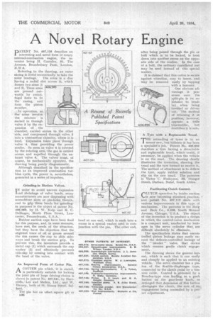
PATENT No, 407,135 describes an interesting and novel form pi rotary internal-combustion engine, the inventor being H. CoataIen, 51, The• Avenue, Brondesbury Park, London, N.W.6. ., Referring to the drawing, an outer casing is bored eccentrically to take the rotor bearings. The rotor is a disc having a radial slot across it, which houses two arms (1 and 2). These arms are pressed. out-wards. by centrifugal force to fit the casing, : and form the piston member.
.
In operation, as :the arms ievolve the mixture is sucked in through valve 3 by the expansion of . the chamber, carried across to the other 'side; and compressed through valve 5 into a cenitibustion chamber, where it is tired. 'Expansion takes place through valve 4,• thus providing the power stroke. So soon as valve 4 is covered by the rotating .arm, the gas is carried across and expelled through the exhaust 'valve 6. The valves rmust, of course, be mechanically operated, the drawing being purely diagrammatic,
Although described in the specification as an improved combustion turbine cycle, the power is, nevrrtheless, generated in a series of impulsr.
Grinding-in Slorless Valves.
I N order to avoid uneven expansion and Shrinkage of valve heads, many manufacturers are now dispensing with. screwdriver slots or pin-holes therein, and to grip these heads for grinding-. in purposes is the object of patent NO. 406,989, by H; W. Kulp and M. C. Dellinger, North Plum Street, Lancaster, Pennsylvania, U.S.A.
Rubber suction cups have been Ased for this purpose, and, in sonic. Measure, have met, the needs of the ituation,
l but they have the objection that the, slightest trace of oil or grea around the rim causes the cup to Aide sideways and break the suction rip. To prevent this, the inventors rovicle a metal cap (1) which surround the cup washer (2) and effectively prevents side-slip by coming into contact with the head of the valve.
An Improved Form of Cotter Pin.
ACO-ITER pin which, it is stated, is particularly suitable for locking the joint pin of large driving: chains is shown in patent No, 407,041,1 by Hartcliffe, i Lee and Malkin, Ltd. and W. Harney, both of St. Simon Street, Salford.
". The pin has an ollset.square gib or B46 head at one end, which is sunk into a recess in a special washer wed in conjunction with the pin. The other end, after being passed through the pin or bolt which is to be locked, is bent down into another recess on the opposite side of the washer. In the case of a bolt, the ordinary castellated nut may he used instead of this special washer.
It is claimed that this cotter is secnre against vibration, easy to insert, and, may be removed easily by tapping with a hammer.
One obvious advantage it possesses over the split-pin is its resistance to bending when being insetted or driven out, The method of retaining it in position, however; appears. a trifle unscientific, but doubtless it is safe.
A Tyre with a Replaceable Tread.
THE retreading of tyres is by no means new, but hitherto it has been a specialist's job. Patent No. 406,896 describes a tyre having a detachable and replaceable tread, which could, if necessary, be applied when the vehicle is on the road. The drawing clearly illustrates the invention, showing the : tread and the tyre formed to receive it. The "method of attachment is to deflate the tyre, apply rubber solution and slip on the new tread. The patentee is Victor C. Finlayson, 52, Stanger Street; Durban, Natal, South Africa.
Facilitating Clutch Control.
CLUTCH operation by intake suction
now becoming standard practice, and patent No. 407,112 deals with various improvements in this type of .mechanism. The patentee is the Borg and Beck Co., 6,553, South Menard Avenue, Chicago, U.S.A. The object of the invention is to produce a design in which the control-valve mechanism is a compact unit, unaffected by leakages in the servo cylinder that are difficult absolutely to eliminate.
The specification States that uncontrolled Piston leakage may easily exceed the delicate-controlled leakage of the " bleeder" valve, that device which ensures gentle dutch engagement.
The drawing shows the general layout, which is such that it can easily and cheaply be applied to an existing vehicle. The servo chamber has a piston of the flexible-diaphragm type, connected to the clutch pedal by a tension cable. Control is obtained by a Bowden-type wire leading to a push button on the gear-lever knob, so arranged that depression of this button • disengages the clutch, the rate of reengagement being contfolled by a preset adjustment.