 1
1 2
2 3
3 4
4 5
5 6
6 7
7 8
8 9
9 10
10 11
11 12
12 13
13 14
14 15
15 16
16 17
17 18
18 19
19 20
20 21
21 22
22 23
23 24
24 25
25 26
26 27
27 28
28 29
29 30
30 31
31 32
32 33
33 34
34 35
35 36
36 37
37 38
38 39
39 40
40 41
41 42
42 43
43 44
44 45
45 46
46 47
47 48
48 49
49 50
50 51
51 52
52 53
53 54
54 55
55 56
56 57
57 58
58 59
59 60
60 61
61 62
62 63
63 64
64 65
65 66
66 67
67 68
68 69
69 70
70 71
71 72
72 73
73 74
74 75
75 76
76 77
77 78
78 79
79 80
80 81
81 82
82 83
83 84
84 85
85 86
86 87
87 88
88 89
89 90
90 91
91 92
92 93
93 94
94 95
95 96
96 97
97 98
98 99
99 100
100 101
101 102
102 103
103 104
104 105
105 106
106 107
107 108
108 109
109 110
110 111
111 112
112 113
113 114
114 115
115 116
116 117
117 118
118 119
119 120
120 121
121 122
122 123
123 124
124 125
125 126
126 127
127 128
128 129
129 130
130 131
131 132
132 133
133 134
134 135
135 136
136 137
137 138
138 139
139 140
140 141
141 142
142 143
143 144
144 145
145 146
146 147
147 148
148 149
149 150
150 151
151 152
152 153
153 154
154 155
155 156
156 Distributor Pump Cuts Weight and Bulk•
Page 67
If you've noticed an error in this article please click here to report it so we can fix it.
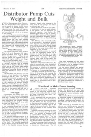
ONE of the surprises of the Commercial Motor Show is the appearance on the stand of Simms Motor Units, Ltd. (240), of a distributor-type fuelinjection pump for small oil engines. It is understood that no experience has yet been obtained with it on a vehicle in this country.
An outsize Perspex model of a pump tor a four-cylindered engine is exhibited alongside a sample of an actual pump which has the type number SPA4Z R/H. • Although it is produced under licence from the American Bosch Corporation, it bears no resemblance to the PSA and PSB models which have previously been manufactured in America Pump Dimensions The overall size of the pump is about 7 in. by 41 in. in diameter, with a projection of about 4 in. by 3 in. which houses the governor. • There is no obvious reason why a pump for a sixcylindered engine need be any larger than the four-cylindered unit.
Mounting could be either horizontal or vertical, provided that a suitable drive could be designed. The drive shaft which runs at half engine speed passes right through the pump and drives the feed-pump, metering device, pumping unit and distributor, which all rotate together.
The feed-pump is at the drive end and consists of an impeller, with flexible vanes that run in a ring. The ring is mounted eccentrically in relation to the impeller blades. As the. blades pass the inlet port, fuel is drawn in. This is due• to the reduction of pressure created when the pockets between the impeller blades enlarge. Subsequently their rotation within the surrounding ring reduces the size of the pockets and the fuel is forced out of the outlet port into the filter, Fuel Supply Filtered fuel, still under slight pressure from the feed-pump, is then piped back into a chamber in the pump which surrounds a shroud on the central shaft. Fuel passes from the chamber through a cross-drilling in the shaft to an axial drilling, also in the shaft.
The cross-drilling sweeps past a slot in the enclosing shroud and it is only when the drilling passes the slot that fuel is transferred to the central passage. The slot in the shroud is shaped so that by varying its axial position, the quantity of fuel delivered to the pumping chamber is controlled.
The pumping chamber consists of a drum which rotates with the drive shaft and carries two opposed plungers in a cross-drilling at right angles to the axis of the shaft. The metered quantity of fuel is forced along the hollow drive shaft to the chamber between the two plungers. Small roller tappets at the outer ends of each plunger run within an internal cam ring.
When the rollers reach the cam lobes. of which there is one for each cylinder of the engine, the two plungers are squeezed together. Just before the pumping takes place a port is opened, because of the rotation of the shaft, and the fuel is displaced through a conventional delivery valve to the distributing portion.
This delivery valve is carried axially in the centre shaft. Beyond the delivery valve the fuel passes through a further cross-drilling in the shaft. This is placed to line up in turn with each of the outlet drillingsin the nump body, which are connected to the injectors.
The mechanical governor is unusual in that its flyweights consist of a number of steel balls held in a cage, rather as in a ball race, but have freedom to move outwards. A conical retainer plate rests on the balls, the. sides of the cone keeping them towards the central shaft.
As engine and pump speed increase, the balls fly outwards and force the conical retainer to move axially along the shaft. The retainer is linked to the metering shroud which controls the quantity of fuel passed to the pumping chamber.
The speed at which the retainer plate moves is determined by varying the compression of a spring which reacts
against the ball retainer plate. The lever which varies tho spring loading is connected to the vehicle accelerator pedal, and an overriding lever is provided for stopping. The main advantage of this pump appears to be its extremely small size as compared with a standard in-line pump with separate plungers.
As the pump plungers are springloaded outwards against the cam ring, their stroke will be constant regardless of the quantity of fuel being injected.
Simms are the first company publicly to display a distributor pump in this country, but it is known that at least one other producer of fuel-injection equipment has been carrying out extensive tests throughout the country on a distributor-type pump.