 1
1 2
2 3
3 4
4 5
5 6
6 7
7 8
8 9
9 10
10 11
11 12
12 13
13 14
14 15
15 16
16 17
17 18
18 19
19 20
20 21
21 22
22 23
23 24
24 25
25 26
26 27
27 28
28 29
29 30
30 31
31 32
32 33
33 34
34 35
35 36
36 37
37 38
38 39
39 40
40 41
41 42
42 43
43 44
44 45
45 46
46 47
47 48
48 49
49 50
50 51
51 52
52 53
53 54
54 55
55 56
56 57
57 58
58 59
59 60
60 61
61 62
62 63
63 64
64 65
65 66
66 67
67 68
68 69
69 70
70 71
71 72
72 73
73 74
74 75
75 76
76 77
77 78
78 79
79 80
80 81
81 82
82 83
83 84
84 85
85 86
86 87
87 88
88 89
89 90
90 91
91 92
92 93
93 94
94 95
95 96
96 97
97 98
98 99
99 100
100 101
101 102
102 103
103 104
104 105
105 106
106 107
107 108
108 109
109 110
110 111
111 112
112 113
113 114
114 115
115 116
116 117
117 118
118 119
119 120
120 121
121 122
122 123
123 124
124 125
125 126
126 127
127 128
128 129
129 130
130 131
131 132
132 133
133 134
134 135
135 136
136 137
137 138
138 139
139 140
140 141
141 142
142 143
143 144
144 145
145 146
146 147
147 148
148 149
149 150
150 151
151 152
152 153
153 154
154 155
155 156
156 157
157 158
158 159
159 160
160 161
161 162
162 163
163 164
164 165
165 166
166 167
167 168
168 169
169 170
170 171
171 172
172 173
173 174
174 175
175 176
176 177
177 178
178 179
179 180
180 181
181 182
182 183
183 184
184 185
185 186
186 187
187 188
188 189
189 190
190 191
191 192
192 193
193 194
194 195
195 196
196 197
197 198
198 199
199 200
200 201
201 202
202 203
203 204
204 205
205 206
206 207
207 208
208 209
209 210
210 211
211 212
212 213
213 214
214 215
215 216
216 217
217 218
218 219
219 220
220 221
221 222
222 223
223 224
224 225
225 226
226 227
227 228
228 229
229 230
230 231
231 232
232 233
233 234
234 235
235 236
236 Control Valve tor Compressed Air Braking
Page 158
If you've noticed an error in this article please click here to report it so we can fix it.
A Résumé of Recently Published Patent Specifications
OPERATION of trailer brakes by —,compressed air is the subject of patent No. 602.485, which comes from Servo-Frein Dewandre S.A., Liege, Belgium. The patent. is chiefly con • cerned with the control valve operated by the driver's pedal.
It is necessary first to understand the action of the 'trailer braking system. This is powered from a compressed-air reservoir carried on the trailer, hut the controlling factor is a pipe system leading to the tractor, and operated, not by pressure. but by a fall in pressure. This means that should the trailer break away, the pressure-drop in the coupling pipe would instantly cause full braking action on the trailer.
The drawing shows the driveroperated valve for producing the opera tive pressure-drop. Main pressure is applied via the ;nlet (I) and passes through the cenue (2) of a piston (3) controlled by a pedal (4). The air . then passes through a port (5) and a pipe (6) and maintains the system in the non-operative zondition.
When the pedal is depressed, it pulls the piston up to a valvehead. (7) which then in effect, becomes part of the piston. This action cuts off the main airsupply, and causes the piston to " feel " the pressure and oppose the driver's effort. At the same time a valve (8) is pulled leftwards, opening an escape port (9) which drops the pressure in the trailer system and causes the brakes to be applied A slight end-play in the central valve-rod enables a state of equilibrium to be established at any degree of braking.
ONE-PIECE CLUTCH PLATES
THE usual type of clutch plate is one having a steel centre member with riveted-on friction facings, the reason being that the steel. and the friction
material have different functions to perform, and no one material can be found to do both duties. To employ a one-piece moulding for the plate is the aim of a scheme outlined in patent No. 601,790, by Ferodo, Ltd., and W. Hall, both of Sovereign Works,, Chapel-en-le-Frith, Stockport.
The drawing shows the component parts of the plate before being united. The rings 1 and 2 are made of suitable friction material, whilst ring 3 and a32
discs 4 and 5 are formed in a material chosen for its mechanical strength. The five pieces are then bonded into a unit by heat treatment, after which the centre is bored and splined. Details of the material are not given, except that it has a cloth base and is impregnated with suitable varnish. Although the proportions shown are not suitable for a motor vehicle, doubtless the shape could be modified for this purpose.
ELECTRO-MAGNETIC TRANSMISSION IMPROVEMENTS THE Cotal magnetic transmission is already well known, and the latest
modifications ate brought forward in patent No. 602,497, by Societe D'application des Brevets Cotal, Neuilly-sur-. Seine, France. Several designs are shown, the one illustrated being suitable for a heavy lorry. The main feature of the patent is not so much the changespeed mechanism as the clutching and reversing arrangements.
Referring to the drawing, the engine shaft ill drives, primarily, a magnetic clutch (2) and the sunwheel (3) of an epicyclic gear. The outer annulus of the gear forms the output shaft (4) whilst the planet-carrier (5), free on its shaft, can be magnetically gripped by either the primary clutch or by a stationary magnet (6). According to which magnet is operated, a forward or reverse drive is transmitted to the output shaft. A further feature is the provision of another magnet (7) which can grip the annulus member and function as an electric brake.
The rest of the parts are electrically operated two-speed gears: there are three sets of these, all coupled in series, an arrangement which, by selective clutching, will give eight speed ratios.
• THE HEAT-TREATMENT O‘F CARBURIZING STEEL PATENT No. 601.755 comes from Guy Motors, Ltd_ and W. Woodward, both of Fallings Park, Wolverhampton, and makes some suggestions on the subject of the case-hardening of alloy steels.
According to the patent, the usual treatment is as follows: The steel is first carburized for 12 hours at 900 degrees C., quenched at 840 degrees C., quenched again at 770 degrees C., and finally tempered for about lf hours at 170 degrees C. This method is rather inclined to leave a semi-soft layer just under the surface, where it is often exposed by grinding, the reason being that some of the austenite in the alloy has not been converted into the harder martensite.
The proposed remedy is to modify the heat-treatment to the following: First a normal carburizing operation and then to coal the piece to a sub-zero temperature immediately afterwards, followed by a temper ing operation. The 1 ow temperature mentioned is minus 75 degrees C., but no details are given as to how it is applied to the work.
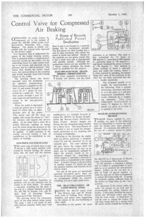
TRAILER OVER-RUNNING BRAKES
TRAILER brakes, applied by over running, are open to the objection that it is impossible to reverse the outfit until the brakes have been manually released. To overcome this difficulty is the aim of a scheme shown in patent No. 602,525, by J. Isherwood, 16, Marsh Lane, Charlemont, West Bromwich.
To the drawbar is attached a sliding rod (1) which is spring-loaded at both ends so as to maintain the mid-position shown. Collars on the rod abut on a pair of forks (2) geared together by teeth (3), and one of them is lengthened to actuate the brake cable (4). A spring (5) normally applies sufficient force tb the brakes to keep them in the "on " position.
In operation, if the tractor pulls, the collar (6) presses on its fork and by overpowering the spring, releases the brakes. Conversely, backing the tractor moves the left-hand collar and fork, with the same result. A hand-lever (7) cad be used to release the brakes, the rod then being held by a spring catch (8) which latches behind the towing eye.